EasyManua.ls Logo

Mitsubishi Electric CR760-D - Page 689

Mitsubishi Electric CR760-D
730 pages
To Next Page IconTo Next Page
To Previous Page IconTo Previous Page
Loading...
7Appendix
Spline interpolation Appendix-669
Sample program
The path 1 path point data is registered in spline file 05. Spline interpolation is executed on path 1 and path
2 by using frame transformation. At this time, the path point data numerical settings are used by the slot 2
program to turn the output signal No. 100 and No. 101 signals ON and OFF during the movement.
Fig.7-103:Movement of sample program
Slot 1
+X
+Y
開始位置
-1
数値設定
経路3
PR1
PR2
PR3
PC1
PC3
PC2
終了位置
1
-1
0
0
2
経路1
経路2
出力100
ON
-1
出力100
OFF
出力101
ON
出力101
OFF
100 ON
100 OFF
力101 ON
101 OFF
1
0
-1
Output 101 OFF
Output 101 ON
Output 100 OFF
Output 100 ON
Path 2
Output 101
Output 101
Output 100
Output 100
Numerical
setting value
Path 1
End position
Path point 3
Start position
Ovrd 100
Mov P1 ‘ Move to wait position (P1) with joint interpolation
Fine 200 ‘ Change positioning pulse to 200
Spd 100 ‘ Set linear interpolation speed to start position to 100mm/s
M_00=1 ‘ Turn slot 2 synchronization flag ON
MvSpl 5, 50, 10
Spline interpolate path 1 with acceleration/decelerate distance
50mm/s
M_00=0 ‘ Turn synchronization flag OFF
Fine 0 ‘ Disable positioning pulse designation
Mvs P1 ‘ Move to wait position with linear interpolation
PR1=(0, 0, 0, 0, 0, 0)(0, 0) ‘ Set the reference coordinate system for frame transformation
(PR1 to PR3)
PR2=(20, 0, 0, 0, 0, 0)(0, 0)
PR3=(0, 20, 0, 0, 0, 0)(0, 0)
PC1=(0, 40, 0, 0, 0, 0)(0, 0) ‘ Set the position of the transformed reference coordinate system
(PC1 to PC3)
PC2=(0, 60, 0, 0, 0, 0)(0, 0) ‘ (90-degree turn around Z axis in respect to pre-transformation,
PC3=(-20, 40, 0, 0, 0, 0)(0, 0) ‘ coordinate system moved 40mm in Y axis direction)
SetCalFrm PR1, PR2, PR3, PC1, PC2, PC3 ‘ Calculate and set coordinate system for frame transformation
Fine 200
M_00=1
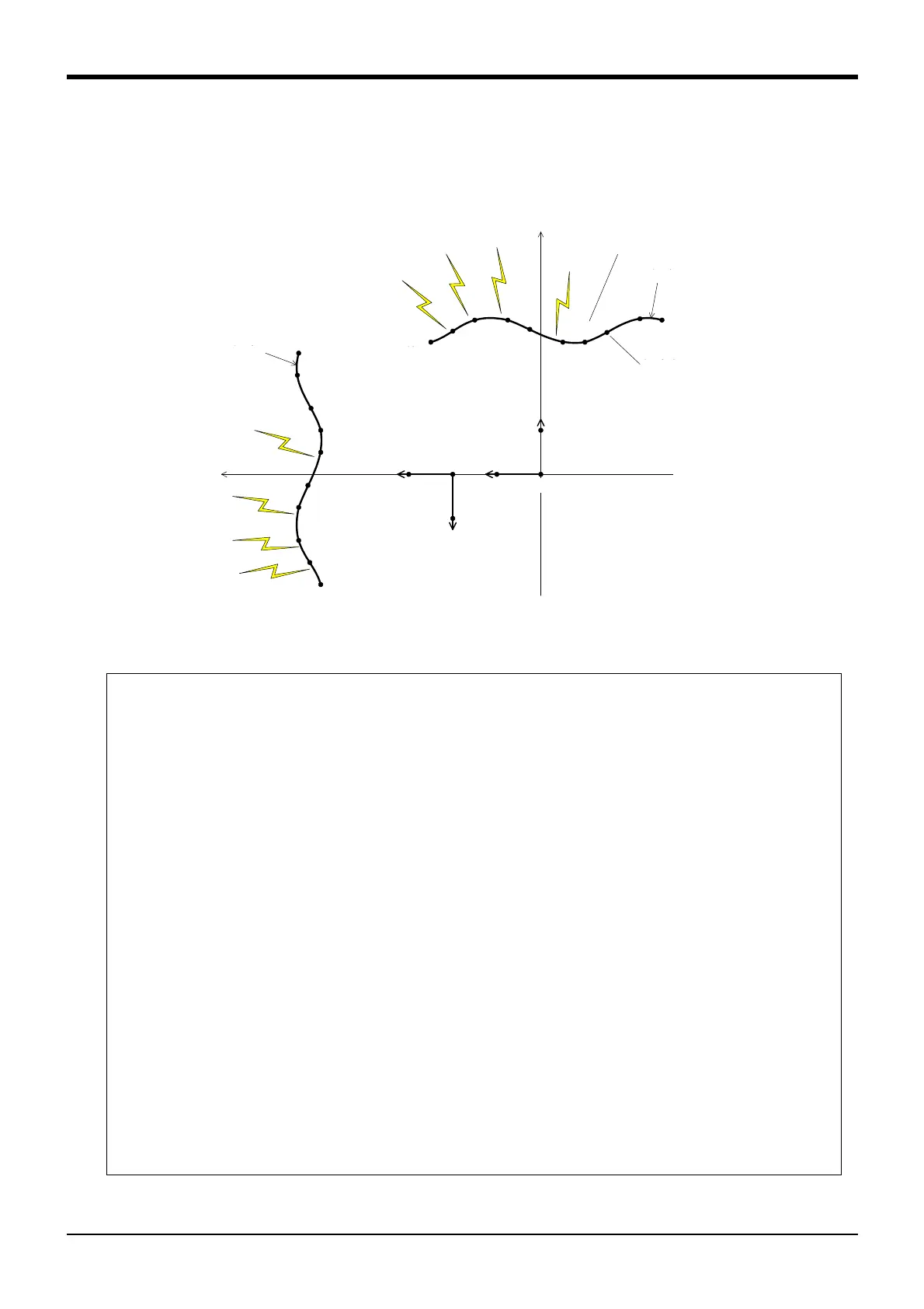
MvSpl 5, 50, 10, 2 ‘ Execute frame transformation on spline No. 5 path point
‘ and spline interpolation path 2
M_00=0
Fine 0
Mvs P1
End

Table of Contents

Related product manuals