113
CHAPTER 3 FUNCTIONS
3
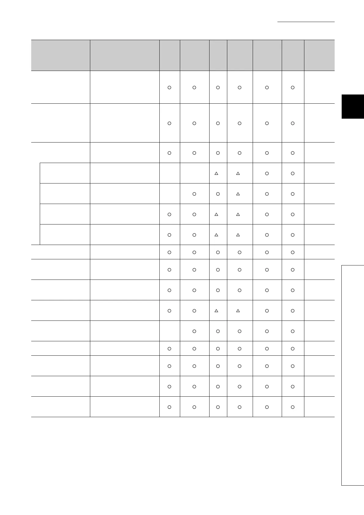
3.1 Function List
H/W error time PLC
operation mode setting
Sets whether to stop or continue
operations in the CPU module
when a hardware error has
occurred in an intelligent function
module or interrupt module.
Page 142,
Section 3.9
Intelligent function module
switch setting
Makes settings for the intelligent
function modules and interrupt
modules. (Refer to manuals of
intelligent function modules and
interrupt modules for setting
details.)
Page 143,
Section 3.10
Monitor function
Reads the status of programs and
devices in the CPU module using
a programming tool.
Page 145,
Section 3.11
Monitor condition
setting
Specifies the monitoring timing of
the CPU module with device
condition or step number.
××
*1 *1
Page 146,
Section
3.11.1
Local device
monitor/test
Monitors and/or tests the local
devices of the specified program
using a programming tool.
×
*1
Page 151,
Section
3.11.2
External input/output
forced on/off
Forcibly turns on/off the external
input/output of the CPU module
using a programming tool.
*1 *1
Page 154,
Section
3.11.3
Executional conditioned
device test
Changes a device value within the
specified step of a sequence
program.
*1 *1
Page 159,
Section
3.11.4
Online change
Writes programs when the CPU
module is in the RUN status.
Page 168,
Section 3.12
Program monitor list
Displays the scan time and
execution status of the program
being executed.
Page 180,
Section
3.13.1
Interrupt program monitor
list
Displays the number of
executions of interrupt programs.
Page 180,
Section
3.13.2
Scan time measurement
Measures the execution time of
the area specified by the steps in
a program.
*1 *1
Page 181,
Section
3.13.3
Sampling trace function
Continuously samples the
specified device data at a preset
timing.
×
Page 184,
Section 3.14
Debug function from multiple
programming tools
Enables simultaneous debugging
by multiple programming tools.
Page 189,
Section 3.15
Watchdog timer
Monitors operational delays
caused by hardware failure or
program error of the CPU module.
Page 193,
Section 3.16
Self-diagnostic function
Self-diagnoses the CPU module
to see whether an error exists or
not.
Page 195,
Section 3.17
Error history
Stores the result of self-
diagnostics to the memory as
error history data.
Page 205,
Section 3.18
Function Description
Q00U
JCPU
Q00UCPU,
Q01UCPU
Q02U
CPU
QnUD(H)
CPU
QnUDE(H)
CPU
QnUDV
CPU,
QnUDP
VCPU
Reference

 Loading...


