160
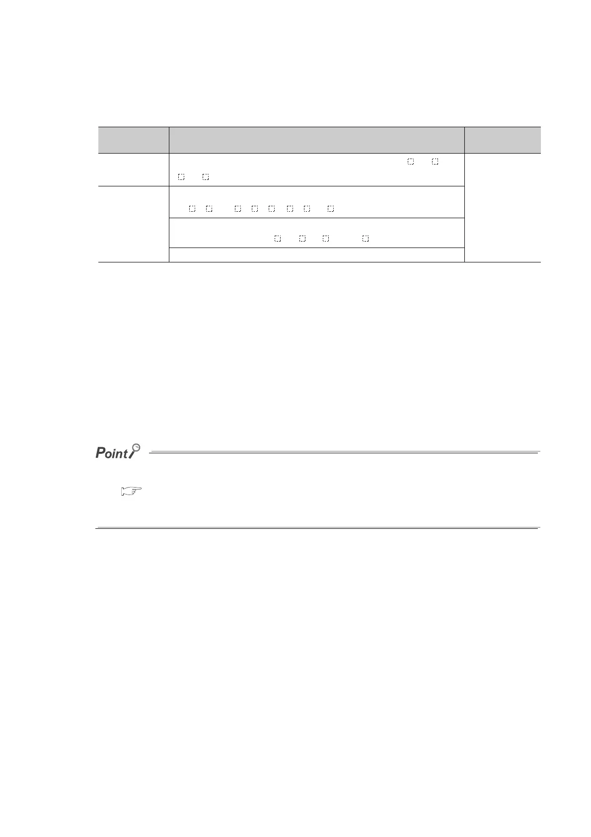
(2) Available devices and number of settable devices
The following table lists available devices and the number of settable devices.
*1 The extended data register (D) is included.
*2 The extended link register (W) is included.
Note, when the write-protect function for device data (from outside the CPU module) is enabled, that indirect
specified/index-modified devices cannot be set for the test. When the write-protected range is set to the file
register (ZR (R)), the file register (R) cannot be set, too.
(3) How to check the execution status
The execution status of registered executional conditioned device test can be checked in three different ways:
• By the display on the screen for checking the registration status in a programming tool
• By the flash of the MODE LED in green
• By the on status of the first bit of SD840 (Debug function usage)
● The MODE LED also flashes in green when the external input/output forced on/off function is used. To check the
execution status using the MODE LED, check the status of the external input/output forced on/off function as well.
( Page 158, Section 3.11.3 (2) (h))
● When using SD840 to check the execution status, remind that SD840 is used to check the status of the external
input/output forced on/off function as well.
Type Available device
Number of
settable devices
Bit device
X, Y, M, L, B, F, SB, V, SM, T (contact), ST (contact), C (contact), J \X, J \Y,
J \B, J \SB, FX, FY, DX, and DY
Up to 32 (in total)
Word device
T (current value), ST (current value), C (current value), D
*1
, SD, W
*2
, SW, R, ZR,
Z, U\G, U3E\G, J\W, J\SW, and FD
Digit-specified bit device:
X, Y, M, L, F, SM, V, B, SB, J \X, J \Y, J \B, and J \SB
Indirect specification (@D0): D, SD, W, SW, R, and ZR (devices specified with @)

 Loading...


