11 TROUBLESHOOTING
11.4 Examples of Troubles with the I/O Module
107
11
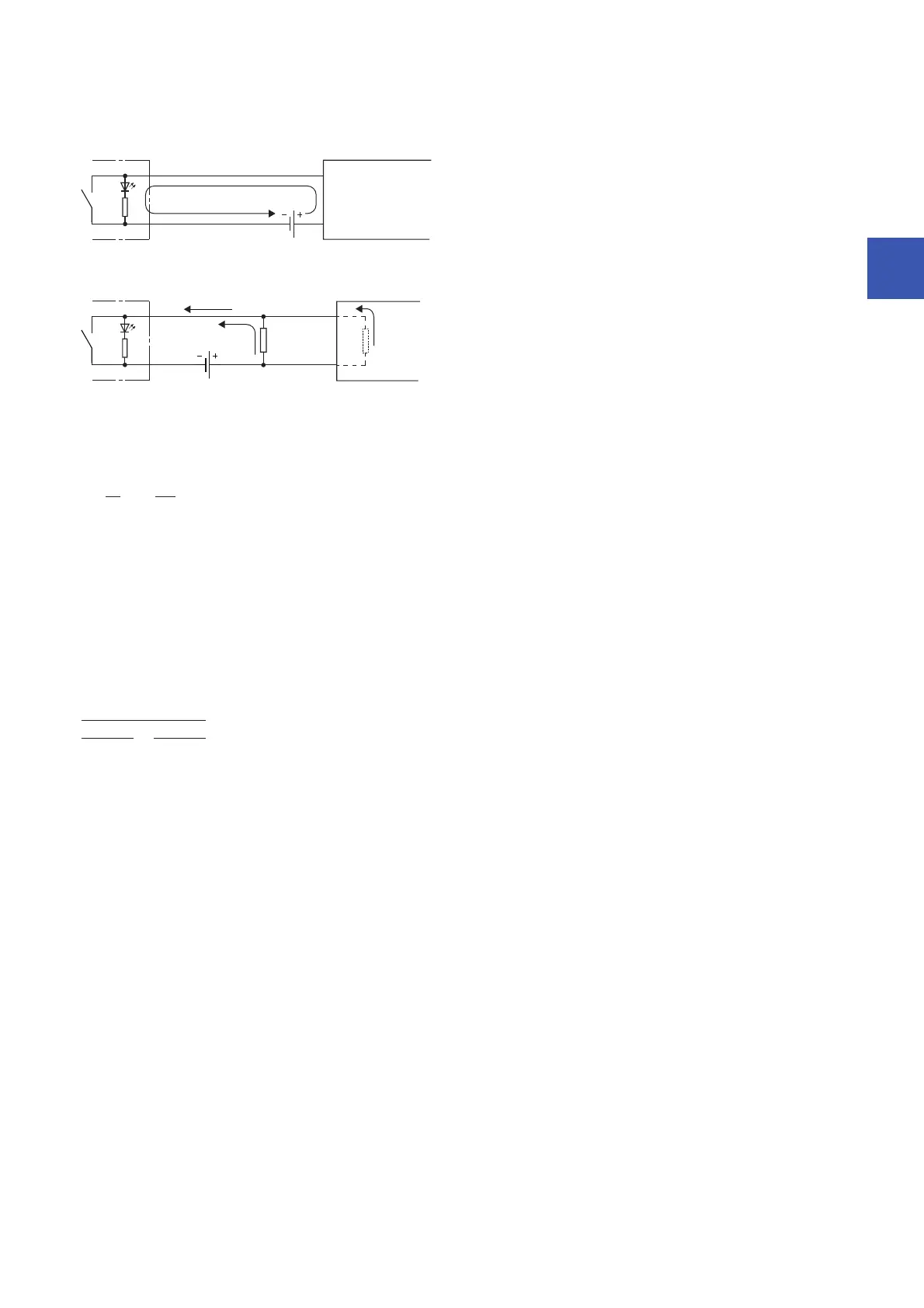
■Calculation example
If the switch with LED indicator with maximum leakage current of 3mA when 24VDC is supplied to the NZ2MFB1-32D is
connected
1. The OFF current of NZ2MFB1-32D is not 1.7mA or lower. Therefore, connect a resistor as shown below.
Z: Input impedance
2. To satisfy the condition that the OFF current of NZ2MFB1-32D is 1.7mA or lower, the current through the connected
resistor should be 1.3mA or higher. From the formula below, the connected resistor (R) is 4.97k or lower.
3. When the resistor (R) is 2.7k, for example, the power capacity (W) of the resistor (R) becomes 0.308W.
V: Input voltage
4. Because the resistor requires the power capacity of 3 to 5 times as large as the actual current consumption, the resistor
connected to the terminal should be 2.7k; and 1 to 2W.
5. OFF voltage when the resistor (R) is connected becomes 4.74V. This satisfies that the OFF voltage of NZ2MFB1-32D is
5V or lower.
Input module
Leakage current 3mA
24VDC
Z = 3.8kΩ
I
R = 1.3mA
3mA
Iz = 1.7mA
24VDC
Resistor
R ≤
I
R
IZ
1.3
1.7
× Z = × 3.8 = 4.97[kΩ]
W = V
2
÷ R = 28.8
2
÷ 2700 = 0.308[W]
× 3[mA] = 4.74[V]
2.7[kΩ]
1
3.8[kΩ]
1
+
1
 Loading...


