28
3 SPECIFICATIONS
3.2 Performance Specifications
Output module
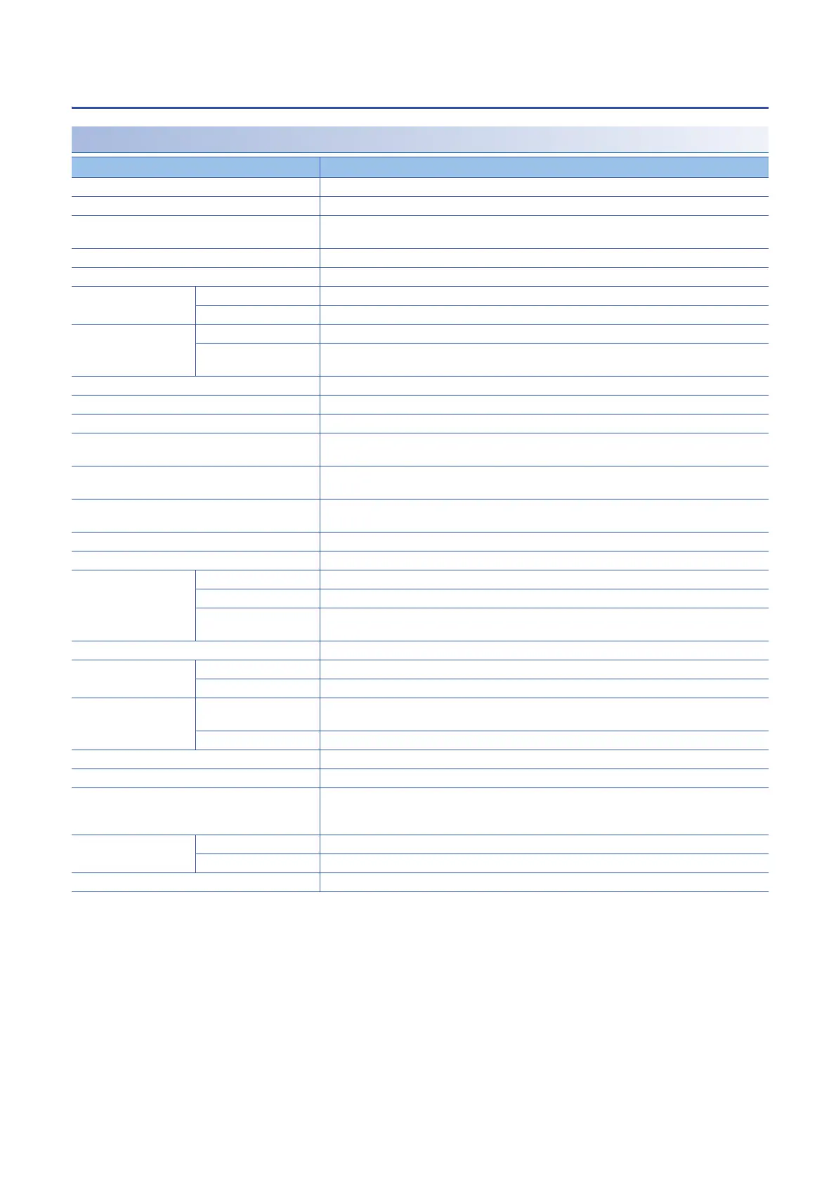
NZ2MFB2-16R contact output module
*1 Only one wire can be connected to a terminal of the terminal block for module power supply and FG. Multiple wires cannot be connected
to a terminal. Connecting two or more wires may cause a poor contact.
*2 It is recommended to use the bar solderless terminal for wiring.
Item NZ2MFB2-16R
Station type Slave station
Number of output points 16 points
Rated switching voltage/current 24VDC 2A (resistance load)/point, 8A/common
240VAC 2A (COS = 1)/point, 8A/common
Minimum switching load 5VDC 1mA
Maximum switching load 264VAC 125VDC
Output response time OFFON 10ms or less
ONOFF 12ms or less
Life Mechanical 20 million times or more
Electrical Rated switching voltage/current load 100 thousand times or more
Page 69 Relay life (contact switching life)
Maximum switching frequency 3600 times/hour
Surge suppressor None
Fuse None
Withstand voltage 2300VACrms for 1 minute between all AC external terminals and the ground
510VACrms for 1 minute between all DC external terminals and the ground
Insulation resistance 10M or higher between all AC external terminals and the ground, all DC external terminals and the
ground (500VDC insulation resistance tester)
Noise immunity Noise voltage: 1500Vp-p (AC type), 500Vp-p (DC type), noise width 1s, noise frequency 25 to 60Hz
(noise simulator condition)
Protection degree IP1X
Wiring method for common 16 points/common (2-wire, screw terminal block type)
External interface Communication part RJ45 connector
Module power supply part Terminal block for module power supply and FG (Two-piece spring clamp terminal block)
I/O part 34-point one-piece terminal block
Tightening torque range for terminal screw (M3 5.2 screw): 0.59 to 0.88Nm
Applicable DIN rail TH35-7.5Fe, TH35-7.5Al (compliant with IEC 60715/JIS C 2812)
Applicable wire size For power supply Stranded wire: 0.3 to 1.5 (22 to 16 AWG), terminal slot size: 2.8mm 2.0mm
*2
For I/O Core: 0.3 to 2.0 (22 to 14 AWG)
Applicable solderless
terminal
Terminal block for module
power supply and FG
*1
Page 81 Applicable solderless terminal
Terminal block for output Page 84 Applicable solderless terminal
Number of occupied stations One station
Reference response time 1ms
Communication cable An Ethernet cable that meets the 100BASE-TX standard
For details, refer to the following.
CC-Link IE Field Network Basic Reference Manual
Module power supply Voltage 24VDC (ripple rate: 5% or less) (Allowable voltage range: 20.4 to 28.8VDC)
Current 153mA or less (24VDC, all points ON)
Weight 0.35kg
 Loading...


