E-35
FX Series PLC User's Manual - Data Communication Edition
Inverter Communication
4 Wiring
4.8 Connection Diagram
A
Common Items
B
N:N Network
C
Parallel Link
D
Computer Link
E
Inverter
Communication
F
Non-Protocol
Communication
(RS/RS2 Instruction)
G
Non-Protocol
Communication
(FX
2N
-232IF)
H
Programming
Communication
I
Remote
Maintenance
Apx.
Discontinued
models
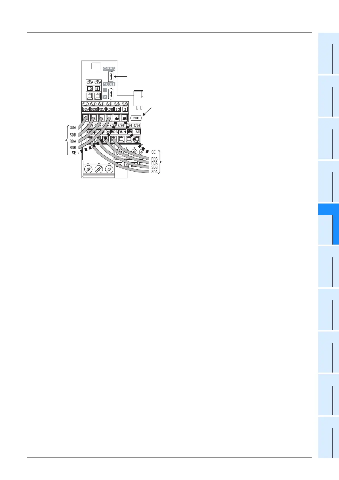
When adopting branches, perform the wiring as shown below: (4-wire type)
When connecting a 100 terminal resistor,
set the switch to the "100 " side.
Ω
Ω
To PLC
To next station inverter
For crossover wiring of a shielded cable using the terminal SG, set the
terminal 2/SG selector switch to the right side (ON) to change over the
terminal 2 to the terminal SG.
(By this setting, analog inputs to the terminal 2 become invalid.)
 Loading...


