M800S/M80/E80 Series Connection and Setup Manual
4 General Specifications
129
IB-1501269-J
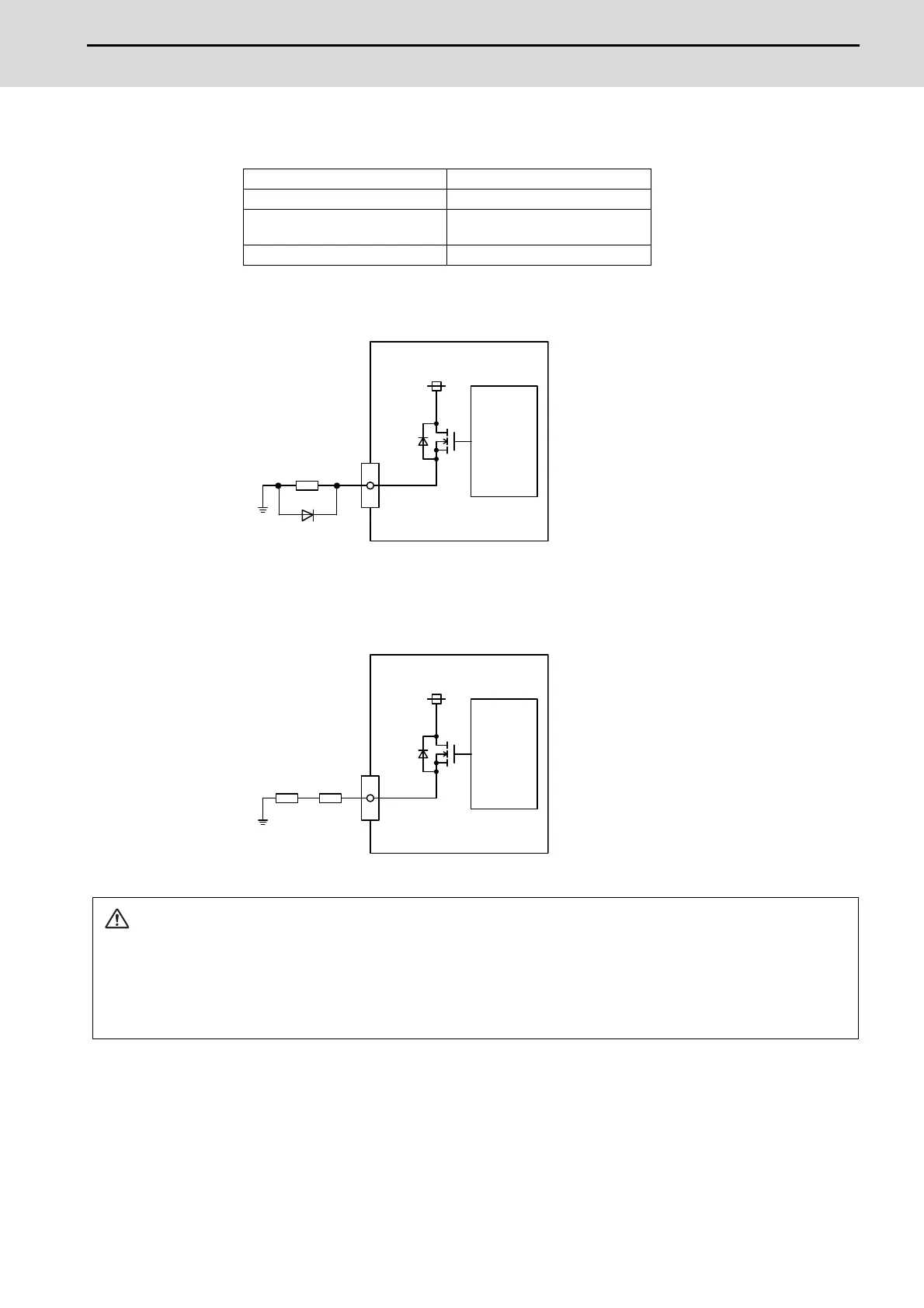
Output conditions
(Note 1) When using an inductive load such as a relay, always connect a diode (voltage resistance
100V or more, twice or more the load current) in parallel to the load.
(Note 2) When the rush current exceeds the maximum output current, always connect a protective
resistor (R=150Ω) serially to the load to suppress rush currents. Make sure that the current is
less than the maximum output current including the momentary current.
Insulation method Photo coupler insulation
Rated load voltage 24VDC
Max. output current
2A/point
8A or less in the whole unit
Output delay time 400μs
CAUTION
1. When using an inductive load such as a relay, always connect a diode in parallel to the load to prevent a
counter-electromotive force.
2. When the rush current exceeds the maximum output current, always connect a protective resistor serially to
the load to suppress rush currents.
Y
24VDC
Source output
Control
circuit
Inductive load
Diode
Y
24VDC
Source output
Control
circuit
Load Resistor

 Loading...


