M800S/M80/E80 Series Connection and Setup Manual
7 Connection of Control Unit
253
IB-1501269-J
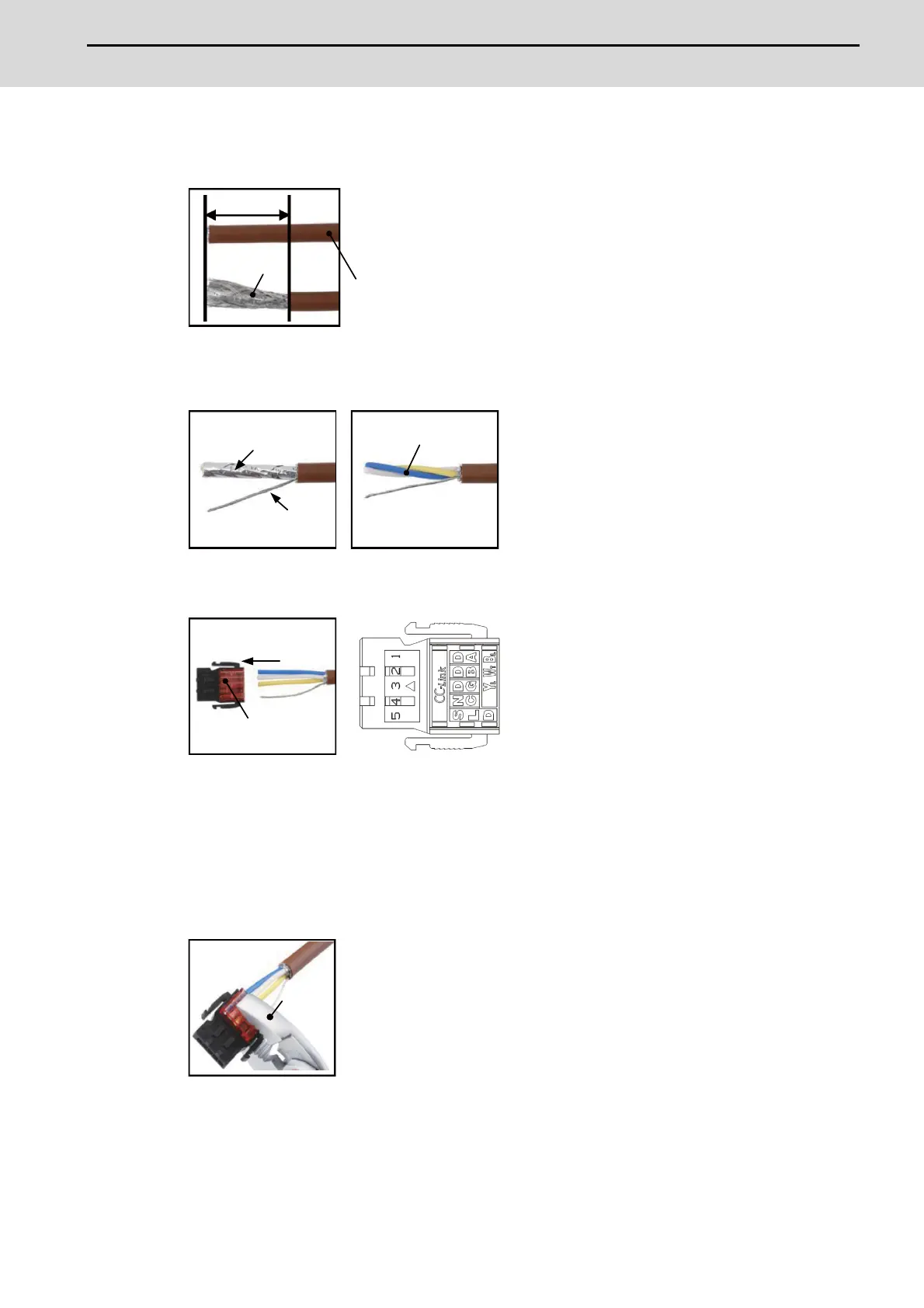
[CC-Link cable connecting procedure]
(1) Remove the sheath of the CC-Link cable about 4cm.
(2) Isolate the shield mesh and the wires coverd with shield tape.
Remove the shield tape from wires.
(3) Insert the wires to the connector for CC-Link as below.
1pin Blue wire (cover notation: DA B)
2pin White wire (cover notation: DB W)
3pin Yellow wire (cover notation: DG Y)
4pin No connect
5pin Shield wire (cover notation: SLD)
(4) Press the connector with the use of a pliers.
Check that the clamp point is flat to the connector for CC-Link.
4cm
Shield mesh
CC-Link cable
twist shield mesh
remove shield tape
wires
Connector for CC-link
Inset
pliers

 Loading...


