_,
.
.
..
.
.
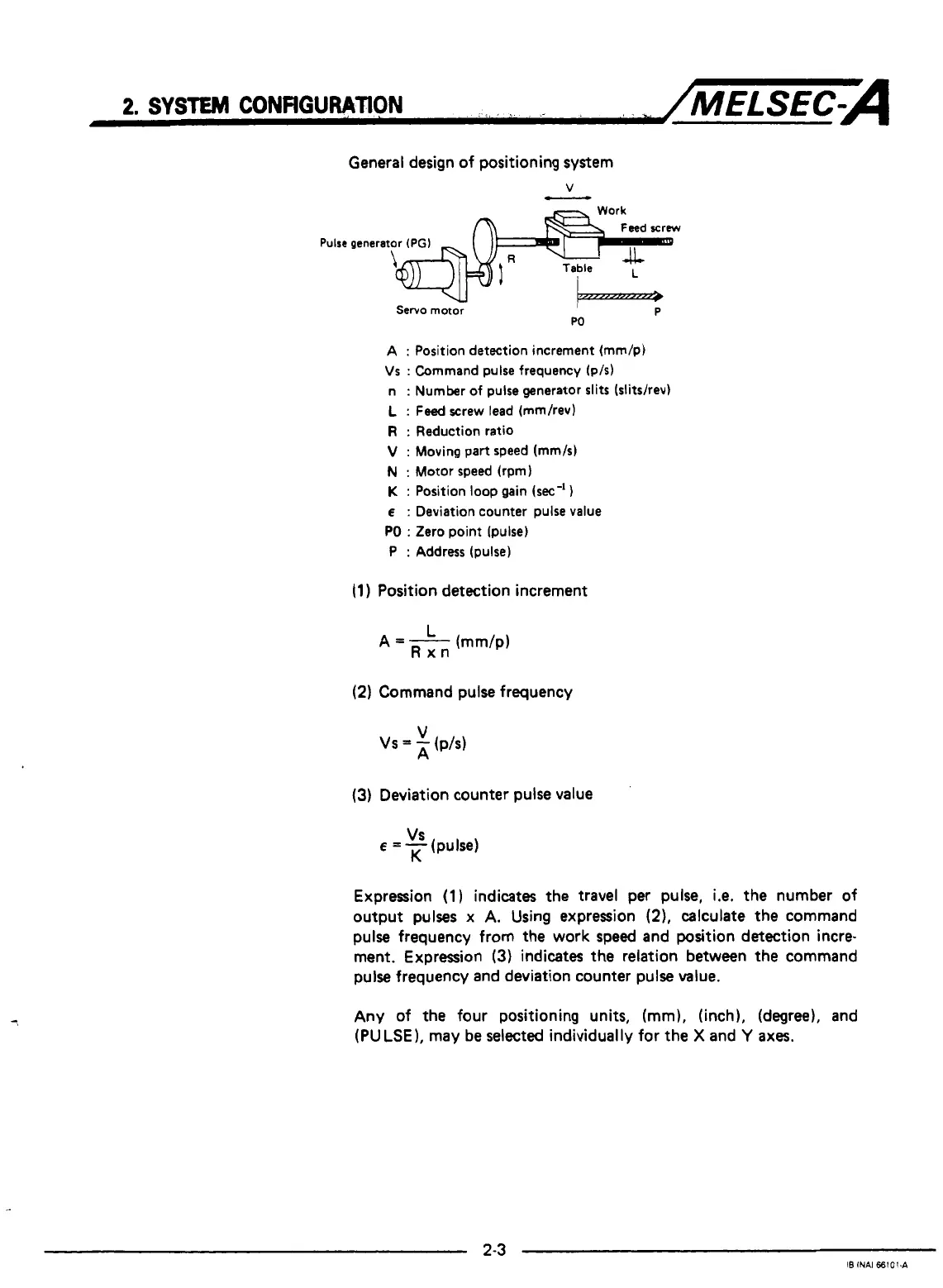
General design of positioning system
Pulse
generator
(PGI
Servo motor
W
P
A
:
Position detection increment (mm/p)
Vs
:
Command pulse frequency (p/s)
n
:
Number
of
pulse generator slits (slitshev)
L
:
Feed
screw lead (mm/rev)
R
:
Reduction ratio
V
:
Moving part speed (mm/s)
N
:
Motor speed (rpm)
K
:
Position
loop
gain
(sec-'
1
E
:
Deviation counter pulse value
PO
:
Zero point (pulse)
P
:
Address (pulse)
(1
)
Position detection increment
(2)
Command pulse frequency
(3)
Deviation counter pulse value
E
=
-
(pulse)
VS
K
Expression
(1)
indicates the travel per pulse,
i.e.
the number of
output pulses
x
A.
Using expression
(2).
calculate the command
pulse frequency from the work speed and position detection incre-
ment. Expression
(3)
indicates
the
relation between the command
pulse frequency and deviation counter pulse value.
Any of the four positioning units, (mm), (inch), (degree), and
(PULSE), may be selected individually for the
X
and
Y
axes.

 Loading...


