3.
SPECIFICATIONS
/MELSEC-A
1
turn
of
PG
-
+
~
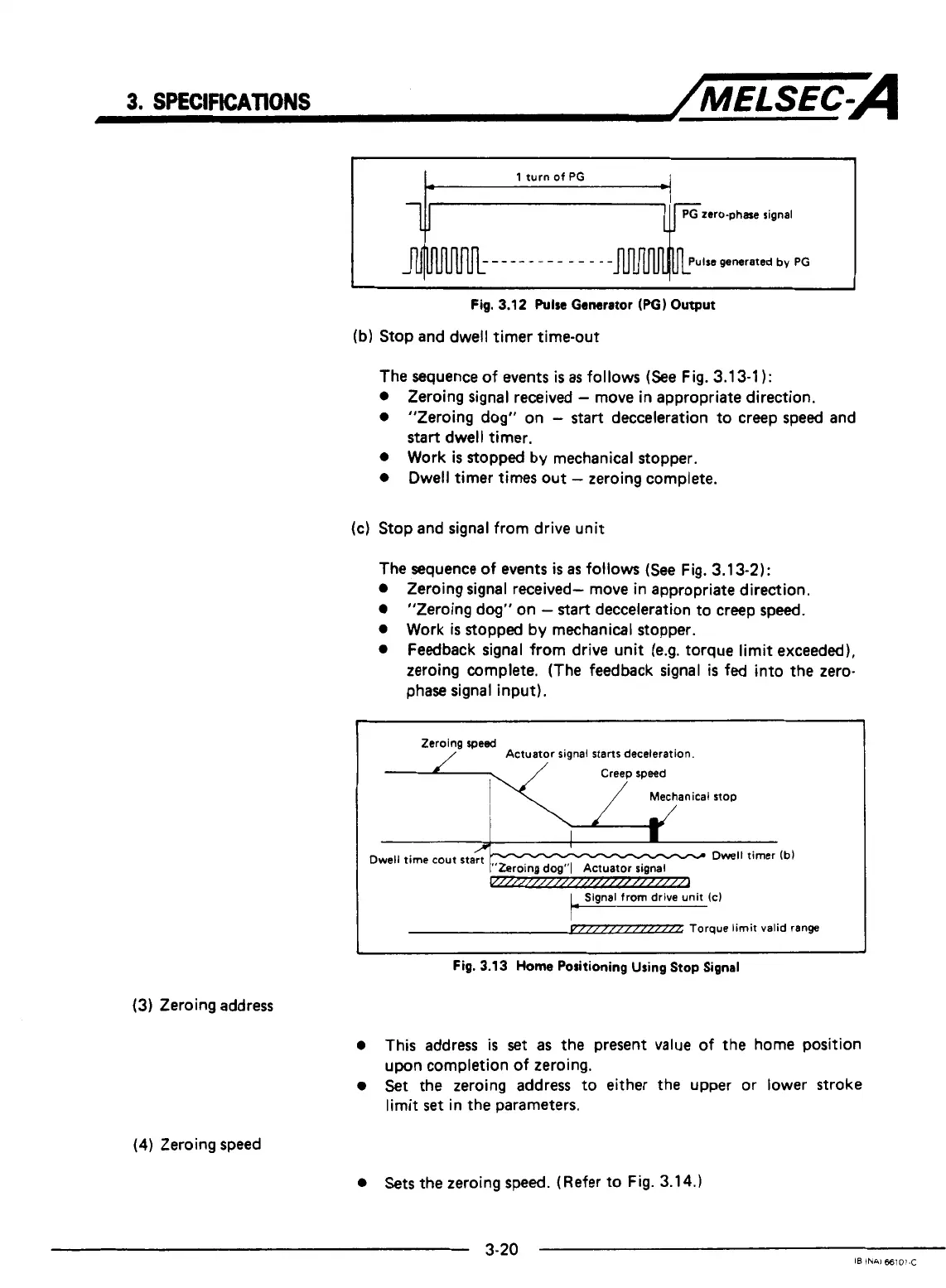
(b) Stop and dwell timer time-out
The sequence of events
is
as
follows (See Fig. 3.13-1
1:
0
Zeroing signal received
-
move in appropriate direction.
0
”Zeroing dog“ on
-
start
decceleration to creep speed and
0
Work
is
stopped by mechanical stopper.
0
Dwell timer times out
-
zeroing complete.
start
dwell timer.
(c)
Stop and signal from drive unit
The sequence
of
events
is
as
follows
(See
Fig. 3.13-2):
0
Zeroing signal received- move in appropriate direction.
0
“Zeroing dog“ on
-
start
decceleration to creep speed.
0
Work
is
stopped by mechanical stopper.
0
Feedback signal from drive unit (e.g. torque limit exceeded),
zeroing complete. (The feedback signal
is
fed into the zero-
phase signal input).
Zeroing
speed
Actuator signal
starts
deceleration.
Creep speed
Mechanical stop
1
Fig.
3.13
Home
Positioning Using
Stop
Signal
(3)
Zeroing address
0
This address
is
set
as
the present value of the home position
0
Set
the zeroing address to either the upper or lower stroke
upon completion of zeroing.
limit
set
in the parameters.
(4) Zeroing speed
0
Sets the zeroing
speed.
(Refer to Fig. 3.14.)
3-20
IB
INAI
66101-C
 Loading...


