127
LDP, LDF, ANDP, ANDF, ORP, ORF
1
2
3
4
5
6
7
8
5.1 Contact Instructions
5.1.2 LDP, LDF, ANDP, ANDF, ORP, ORF
Function
LDP, LDF
(1) LDP is the leading edge pulse operation start instruction, and is ON only at the leading edge of the designated bit device
(when it goes from OFF to ON). If a word device has been designated, it is ON only when the designated bit changes
from 0 to 1.
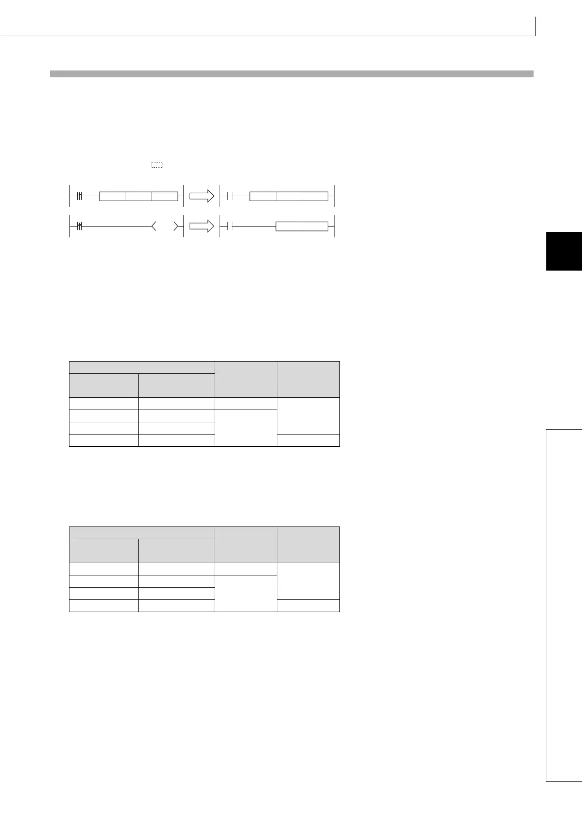
In cases where there is only an LDP instruction, it acts identically to instructions for the creation of a pulse that are
executed during ON( P).
(2) LDF is the trailing edge pulse operation start instruction, and is ON only at the trailing edge of the designated bit device
(when it goes from ON to OFF).
If a word device has been designated, it is ON only when the designated bit changes from 1 to 0.
ANDP, ANDF
(1) ANDP is a leading edge pulse series connection instruction, and ANDF is a trailing edge pulse series connection
instruction. They perform an AND operation with the operation result to that point, and take the resulting value as the
operation result.
The ON/OFF data used by ANDP and ANDF are indicated in the table below:
ORP, ORF
(2) ORP is a leading edge pulse parallel connection instruction, and ORF is a trailing edge pulse serial connection
instruction. They perform an OR operation with the operation result to that point, and take the resulting value as the
operation result.
The ON/OFF data used by ORP and ORF are indicated in the table below:
Device Specified in ANDP or ANDF
ANDP State ANDF State
Bit Device
Bit Designated for
Word Device
OFF
to ON 0 to 1 ON
OFFOFF 0
OFFON 1
ON to OFF 1 to 0 ON
Device Specified in ORP or ORF
ORP State ORF State
Bit Device
Bit Designated for
Word Device
OFF to ON 0 to 1 ON
OFFOFF 0
OFFON 1
ON to OFF 1 to 0 ON
X0
D0K0MOV
M0
X0
Ladder using an LDP instruction
X0
D0K0MOVP
X0
Ladder not using an LDP instruction
M0
PLS

 Loading...

