428
TO, TOP, DTO, DTOP
Remark
1. The value of n1 is specified by the upper 3 digits of hexadecimal 4 digits which represent the head I/O number of an
intelligent function module.
QCPU
LCPU
2. QCPU and LCPU establishe the automatic interlock of the FROM/DFRO instructions.
n1 : Head I/O number of an intelligent function module (BIN 16 bits)
*1
n2 : Head address of the area where data is written (BIN 16 bits)
: Data to be written or head number of the devices where the data to be written is stored (BIN 16/32 bits)
n3 : Number of data blocks to be written (BIN 16 bits)
*1: Specified with the upper three digits when the head I/O number is expressed in 4 hexadecimal digits.
7.8.2 TO, TOP Writing 1-word data to the intellig ent function module
DTO, DTOP Writing 2-word data to t he intelligen t function mo dule
7.8.2
TO, TOP, DTO, DTOP
Setting
Data
Internal Devices
R, ZR
J\
U\G
Zn
Constants
K, H
Other
U
Bit Word Bit Word
n1
n2 ––
–– ––
n3 ––
Power
supply
module
CPUQX10 QX10QX10 QX10
Q68
ADV
QY41
P
QY10 QY10
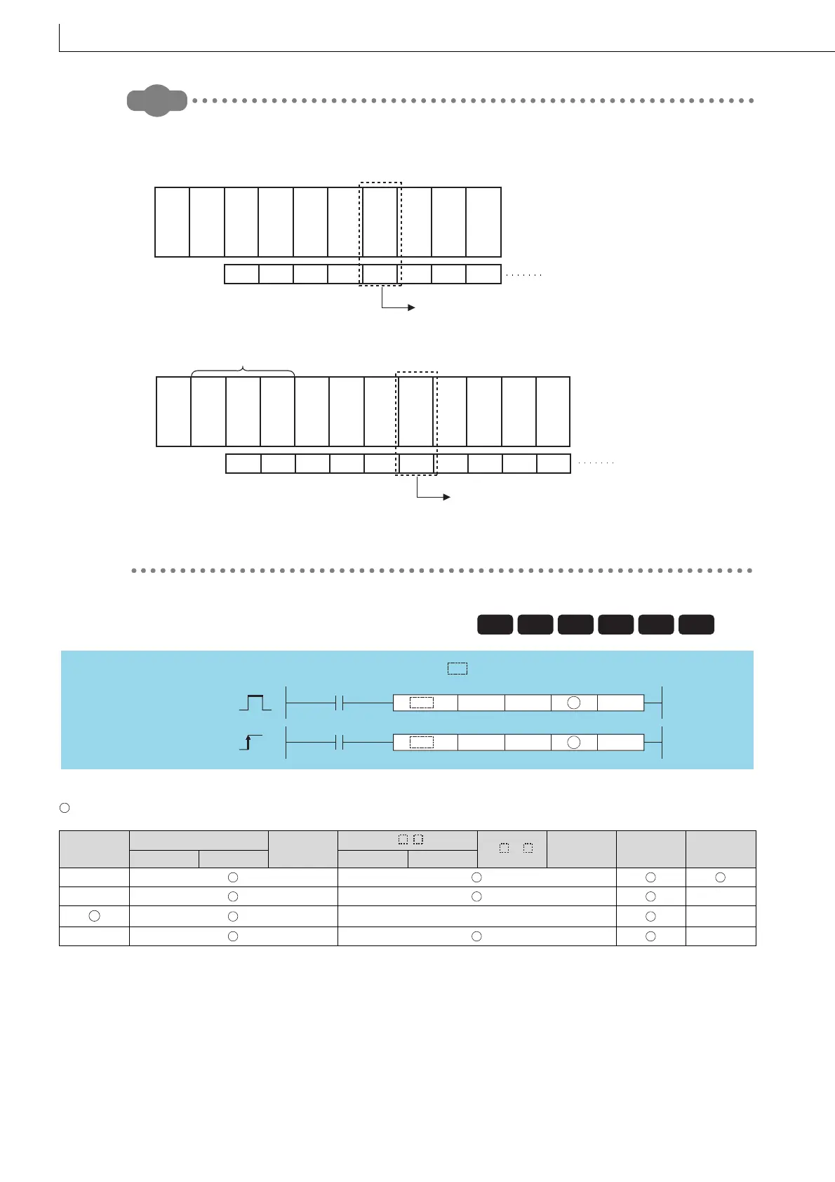
0000
H 0010H 0020H 0030H 0040H 0050H 0070H 0080H
Specify K4 or H4 as the head I/O number to be read.
Head I/O number configured in
the I/O assignment setting
Power
supply
module
CPU Built-in
I/0
Built-in
CC-Link
LX40
C6
LX40
C6
LX40
C6
L60
AD4
LY41
NT1P
LY10
R2
LY10
R2
LY10
R2
0000
H 0010H 0030H 0040H 0050H 0060H 0070H 0090H 00A0H 00B0H
CPU module
(L26CPU-BT)
Specify K6 or H6 as the head I/O number to be read.
Head I/O number configured in
the I/O assignment setting
Basic
Process
High
performance
Redundant
Universal
LCPU
Command
Command
n3
n3P
n1
n1
n2
n2
TO, DTO
TOP, DTOP
S
S
indicates an instruction symbol of TO/DTO.
S
S

 Loading...

