497
EMOD, EMODP
1
2
3
4
4
6
7
8
7.11 Character string processing instructions
7.11.20 EMOD, EMODP
(2) The 7th digit of the significant digits being stored at +1 and +2 is rounded off to make a 6-digit number.
Operation Error
(1) In any of the following cases, an operation error occurs, the error flag (SM0) turns ON, and an error code is stored into
SD0.
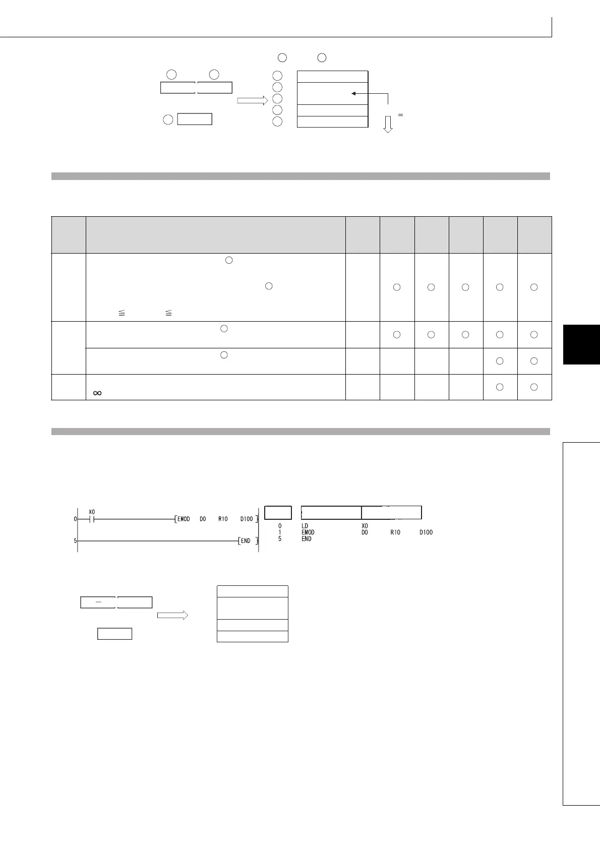
Program Example
(1) The following program breaks down the 32-bit floating decimal point type real number data stored at D0 and D1 into BCD
according to the decimal fraction digits as designated by R10, and stores the results into the area starting from D100
when X0 is turned ON.
[Ladder Mode] [List Mode]
[Operation]
Error
code
Error details
Q00J/
Q00/
Q01
QnH QnPH QnPRH QnU LCPU
4100
The decimal fraction digit specified by is not within the range
between 0 and 7.
The 32-bit floating point real number specified by is not within the
following range:
0. 2
-126
| Device | 2
128
––
4101
The range of the device specified by exceeds that of the
corresponding device.
––
The range of the device specified by exceeds that of the
corresponding device.
–– –– –– ––
4140
The specified device value is -0, unnormalized number, nonnumeric, or
±.
–– –– –– ––
D D
+1
3
0
1234570H
1
3
+4
+3
+2
+1
1
1234570
.
2
3456789
123456789
S1
S2
D
D
D
D
D
S1
Rounded of
S2
S1
D
D
Instruction
Device
Step
D1
D104
D103
D102
D101
D100
R10
0.987654
3
D0
1
9876540
H
1
4

 Loading...

