502
SIND, SINDP
(2) Angles designated at are set in radian units (degrees / 180).
For conversion between degrees and radian values, see the RADD and DEGD instructions.
(3) When the operation results in -0 or an underflow, the result is processed as 0.
Operation Error
(1) In any of the following cases, an operation error occurs, the error flag (SM0) turns ON, and an error code is stored into
SD0.
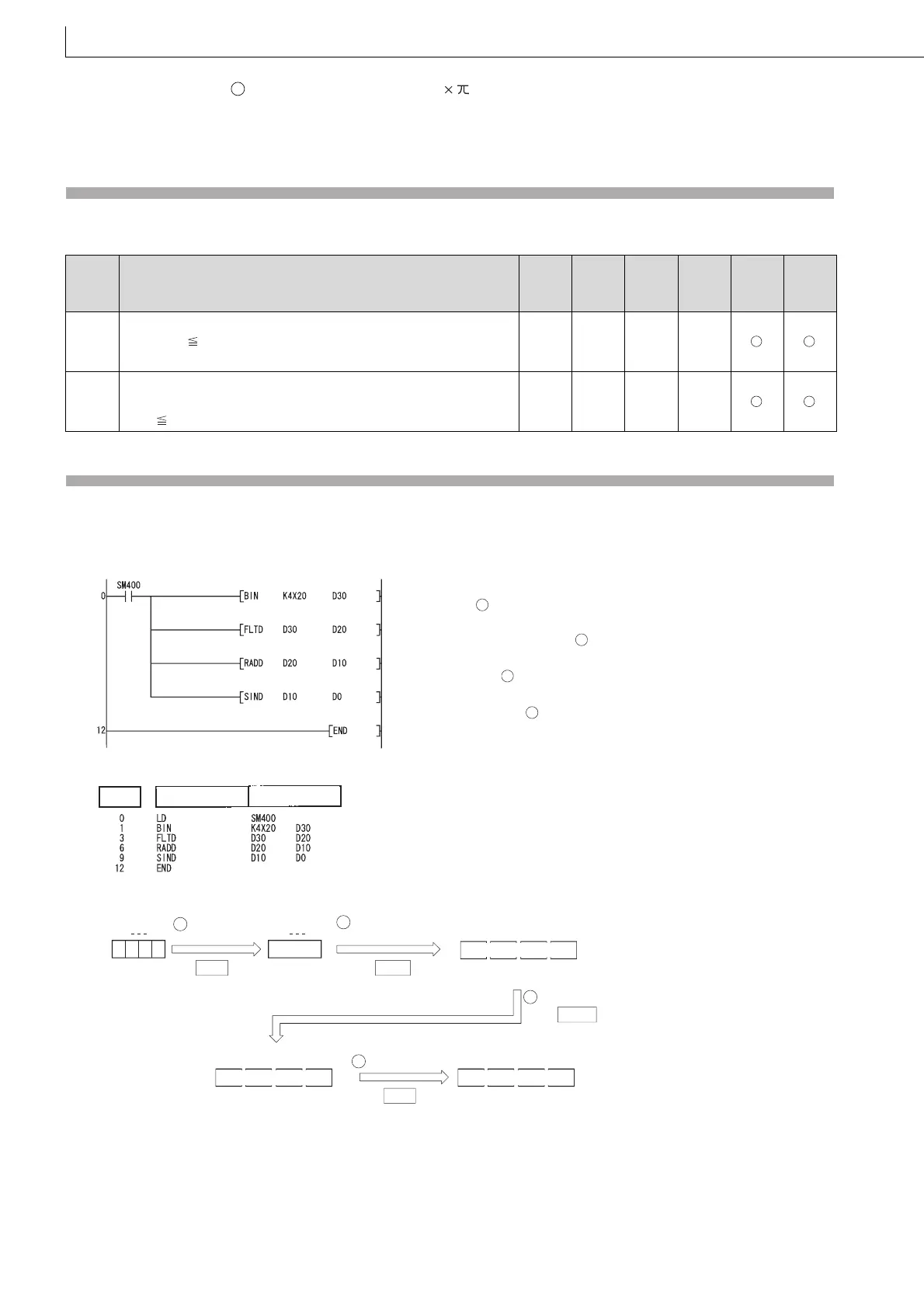
Program Example
(1) The following program conducts a SIN operation on the angles stored in the four BCD digits from X20 to X2F and stores
the results at D0 to D3 as 64-bit floating decimal point type real numbers.
[Ladder Mode]
[List Mode]
[Operations involved when X20 to X2F designate a value of 150]
Error
code
Error details
Q00J/
Q00/
Q01
QnH QnPH QnPRH QnU LCPU
4140
The specified device value is not within the following range:
0, 2
-1022
| Specified device value | < 2
1024
The specified device value is -0.
–– –– –– ––
4141
The operation result exceeds the following range (when an overflow
occurs):
2
1024
| Operation result |
–– –– –– ––
S
Inputs an angle used for
SIN operation ( ).
Converts the input angle into a
64-bit floating-point real number ( ).
Converts the converted angle
into a radian value ( ).
Executes SIN operati
on using the
converted radian value ( )
1
2
3
4
.
Step Instruction Device
64-bit floating-point
real number
X2F
BCD value
0
D30
150
X20
BIN
b15 b0
BIN value
RADD
SIND
150
FLTD
D21
150
D20D23 D22
64-bit floating-point
real number
D11
2.617994
D10D13 D12
64-bit floating-point
real number
D1
0.500000
D0D3 D2
1 Conversion
to BIN
2 Conversion to
floating-point
3 Conversion to radian
4 SIN operation

 Loading...

