2
SYSTEM CONFIGURATION
2.1 System Configuration
2.1.5 Precaution on system configuration
2 - 42
1
OVERVIEW
2
SYSTEM
CONFIGURATION
3
GENERAL
SPECIFICATIONS
4
HARDWARE
SPECIFICATIONS OF
THE CPU MODULE
5
POWER SUPPLY
MODULE
6
BASE UNIT AND
EXTENSION CABLE
7
MEMORY CARD AND
BATTERY
8
CPU MODULE START-
UP PROCEDURES
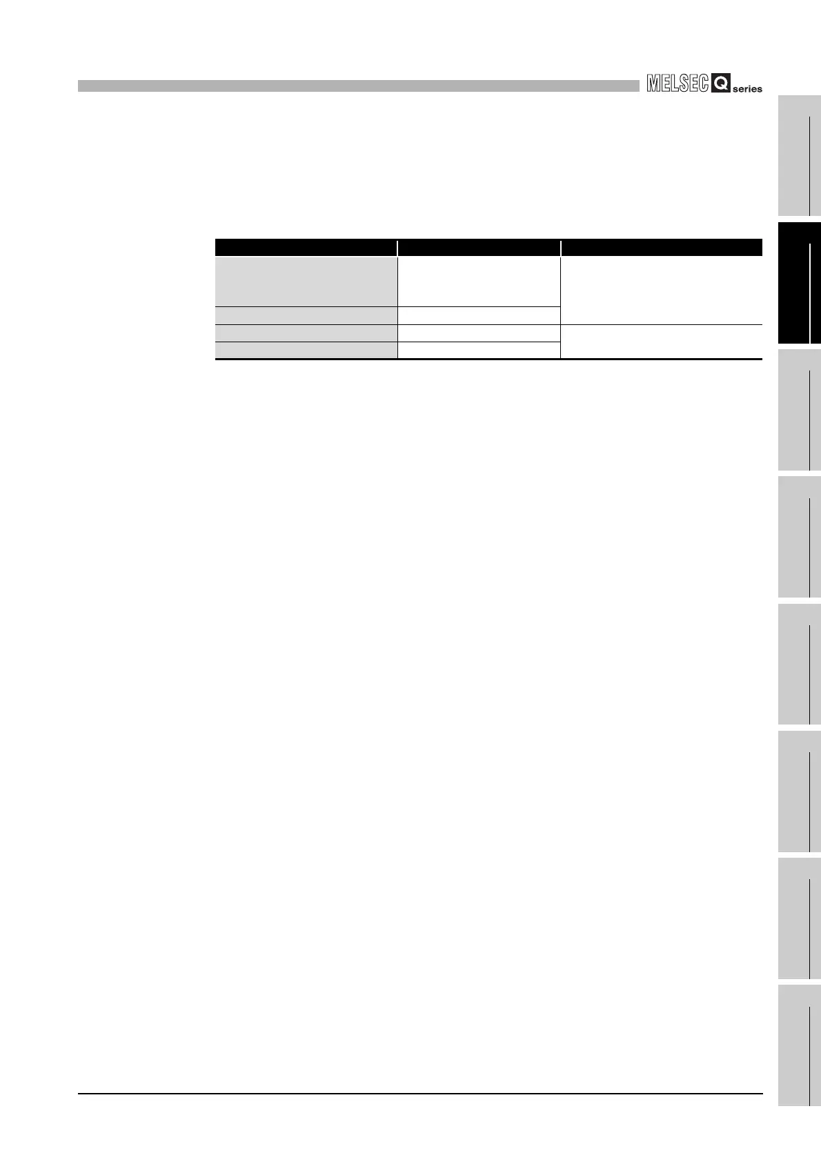
(2) Modules that have restrictions on use of a Built-in Ethernet port QCPU
Table2.13 lists the modules that have restrictions on use of a Built-in Ethernet port
QCPU.
(3) Combination of power supply module, base unit and CPU module
The combination of the power supply module, base unit, and CPU module is
restricted.
(Ex.) The redundant power supply module (Q64RP) can be mounted to the
redundant power main base unit (Q38RB), redundant power extension base
unit (Q68RB), or redundant type extension base unit (Q65WRB) only.
For details, refer to Section 5.1 "Base Unit that Can Be Used in Combination with
Power Supply Module."
Table2.13 Modules that have restrictions on use of a Built-in Ethernet port QCPU
Product name Model First five digits of available serial No.
Serial communication module
• QJ71C24N
• QJ71C24N-R2
• QJ71C24N-R4
10042 or later
Modem interface module • QJ71CMON
Web server module • QJ71WS96
10012 or later
MES interface module • QJ71MES96
 Loading...