4
HARDWARE SPECIFICATIONS OF THE CPU MODULE
4.3 High Performance Model QCPU, Process CPU and Redundant CPU
4.3.1 Part Names
4 - 33
1
OVERVIEW
2
SYSTEM
CONFIGURATION
3
GENERAL
SPECIFICATIONS
4
HARDWARE
SPECIFICATIONS OF
THE CPU MODULE
5
POWER SUPPLY
MODULE
6
BASE UNIT AND
EXTENSION CABLE
7
MEMORY CARD AND
BATTERY
8
CPU MODULE START-
UP PROCEDURES
Table4.8 Part Names
No. Name Application
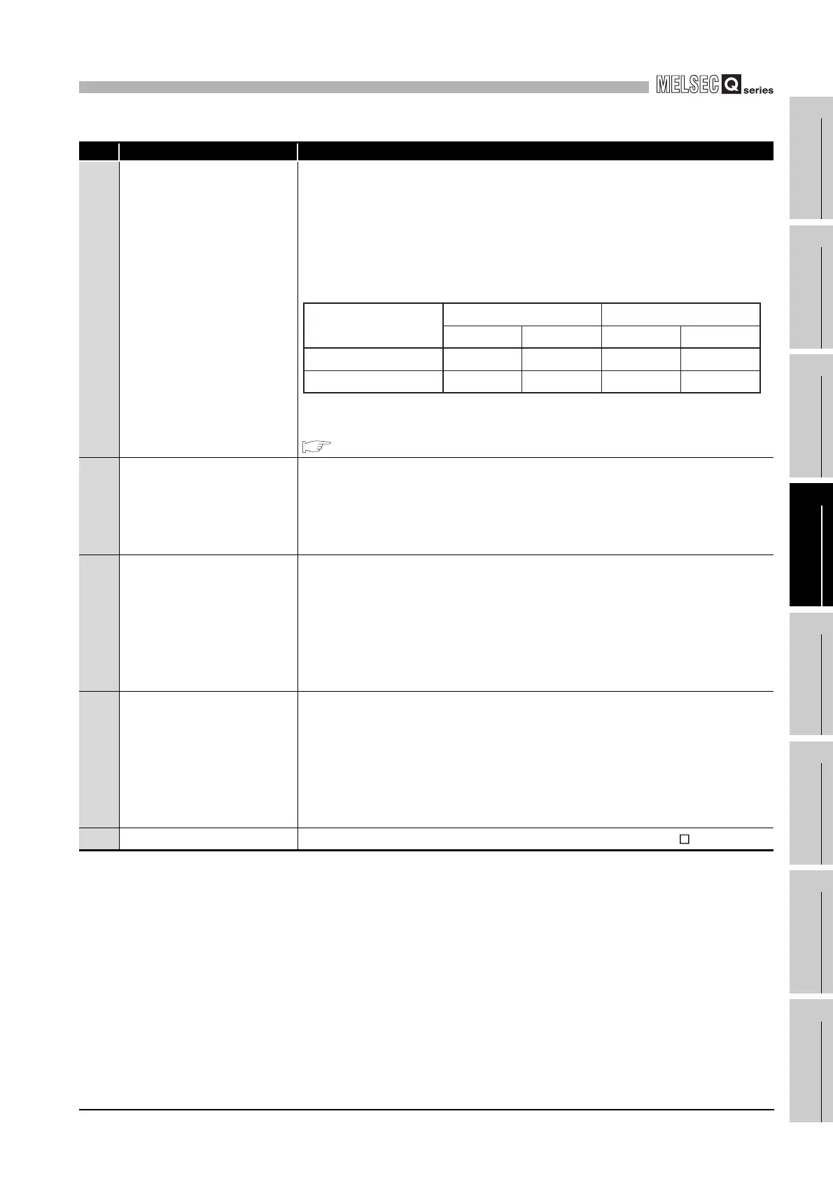
21)
BACKUP LED
*4
Indicates the backup or separate mode while the system is running normally.
ON (green) : Backup mode
OFF (red) : The status in which control (RUN) cannot be continued by system
switching
ON (orange) : Separate mode
OFF : Debug mode
The LED indication is as shown below when the memory copy from control system to
standby system is executed.
For the memory copy from control system to standby system, refer to the manual
below.
QnPRHCPU User's Manual (Redundant System)
22)
CONTROL LED
*4
Indicates the CPU module operates as control system or standby system.
ON : Control system (The standby system is normal and system switching is
available.)
OFF : Standby system
Note that this LED lights up in the debug mode.
23)
SYSTEM A LED
*4
The LED of the CPU module on the system A side lights up.
ON : System A
Flicker : The tracking cable is disconnected while the system runs normally as
system A.
(It lasts until the system A side tracking cable is connected.)
OFF : System B (The SYSTEM B LED lights up.)
Note that this LED lights up in the debug mode.
24)
SYSTEM B LED
*4
The LED of the CPU module on the system B side lights up.
ON : System B
Flicker : The tracking cable is disconnected while the system runs normally as
system B
(It lasts until the system B side tracking cable is connected.)
OFF : System A (The SYSTEM A LED lights up)
Note that this LED goes off in the debug mode.
25)
TRACKING connector
*4
Connector for connecting system A or B with the tracking cable (QC TR).
In backup mode In separate mode
Memory copy executing
Memory copy normally
completed
Control system Standby system Control system Standby system
ON (red) ON (orange)
ON (red) ON (orange)
ON (red) ON (orange)
ON (red) ON (orange)
 Loading...