22 - 51
22. TROUBLESHOOTING
Situation Cause Countermeasure
Example 7
When an external
switch is connected in
parallel between the
output and common,
the voltage between
Y1 and COM1 drops
to between 0 and 24V
even though the
output Y1 which is not
connected to the
external switch is
OFF.
Especially when the
load L2 is relatively
small, (Load current of
several mA only) such
as LED lamps and
photocouplers, the
outputs drop.
AY40
AY41
AY42
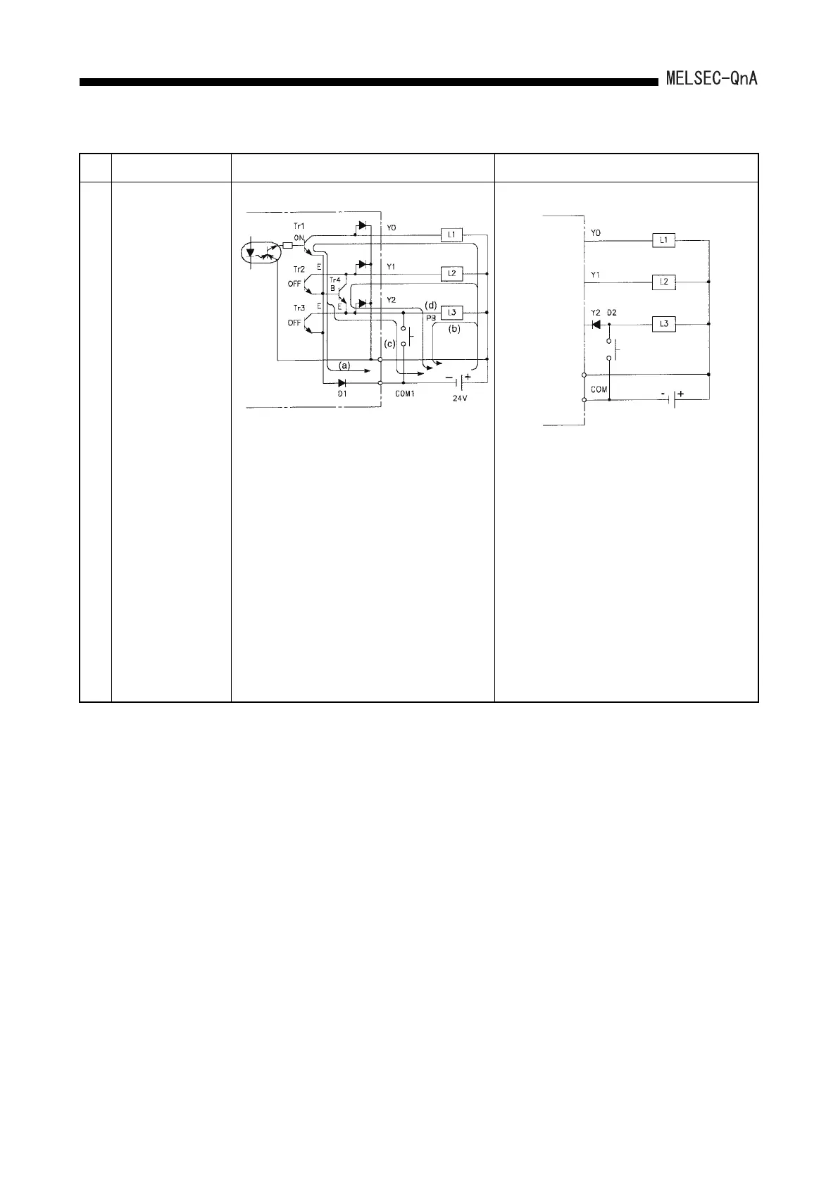
Incorrect output by parasitic transistor (Tr4)
Y2 can turn the load L3 on either from a PC or PB.
When PB is ON, Y0 is ON with a PC, and Y1 is
OFF:
(1) L1 (current (a)) and L3 (current (b)) turn ON.
(2) A potential difference to COM1occurs in the
emitter E of Tr1 to Tr3 since diode D1 is
connected between COM1 and the emitter.
(3) The transistors AY40 to 42, etc., are
accompanied by a parasitic transistor (Tr4).
(4) The potential difference described in (2) above
is supplied between the base (B) of Tr4 and
emitter (E), which causes the base current (c)
to flow. (Tr4 turns ON).
(5) The current in (4) causes the collector current
(d) to flow, and voltage Y1 drops to between 0
and 24V.
Add a diode D2 of the class I
F=1A to the output Y2
to connect an external switch as shown in the
diagram above to prevent current (c) and (d) in the
diagram at left from flowing.
However, check the operation voltage of L3 as the
amount of voltage drop of Y2 at power ON
increases for 0.6 to 1V.
 Loading...

