14.
14 - 3
SELECTING MEMORY CARD MODELS
14.2 Selecting Memory Card Capacity
Select a memory card capacity according to the types and sizes of files to be stored in the
memory card. The sizes of files are calculated using the formulas presented below.
*1 "Device types" represents the number of registered device names.
For example, if D, W, and T are registered, it is 3.
*2 "Device ranges" represents the number of registered range settings.
*3 These files can be transferred from the memory card to the built-in RAM in the boot operation.
*4 The total number of setting ranges is the total number of types of the devices that are set as
local devices.
*5 Decimal fraction of "number of bit device points/16" is rounded up.
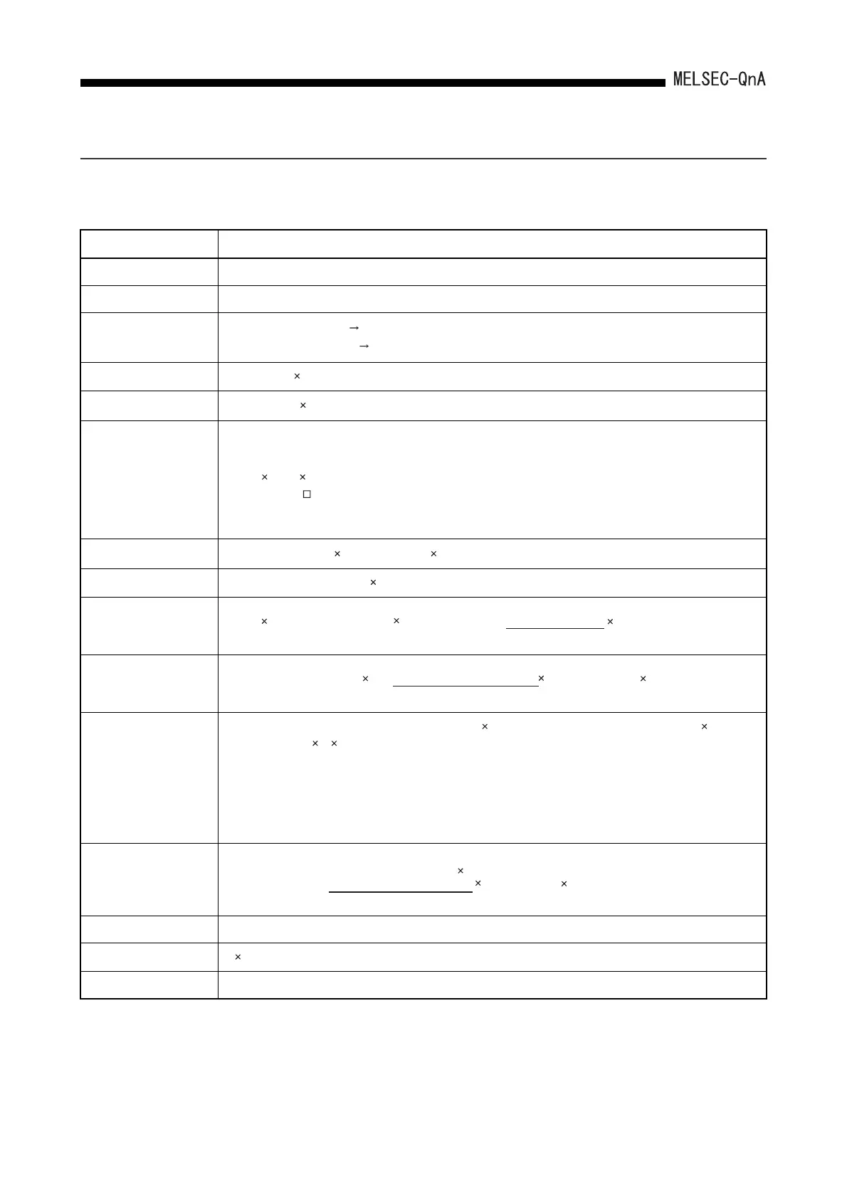
Function Approximate File Capacity (Unit: Bytes)
Drive title 64
Keyword 72
Parameters
*3
MELSECNET, NET/10 None 330
When MELSECNET (II, /B) set Max. 4096 per module
Boot file
(Number of files 18) + 67
Sequence program
*3
(Number of steps 4) + 122
Device comments
*3
(Total commend data size of each device) + 74
• Setting with GX Developer
The comment data size of 1 device is as follows:
10250 a + 40 b + 10 (Quotient of (No. of devices / 256) is substituted for a and the remainder for b.)
• Setting with SW IVD-GPPQ
Although the size varies depending on EMS capacity, it is equivalent to or less than the size obtained in the above DX
Developer case.
Initial device value
*3
(Number of device points 2) + (device types
*1
44) + 66
File register
Number of points for file registers 2 bytes
Local device
Simulation data
Sampling trace data
362 + (No. of word device points + No. of bit device points) 12 + (N1 + N2 + N3 + No. of word device points 2 + (No. of
bit device points/16) 2) trace count (total count)
*5
• According to the items set in the added trace information on the trace device setting screen, the following values are
added forN1 to N3.
(Refer to Section 8.5 (2) (b))
N1: When setting time, "4" is added.
N2: When setting step No., "10" is added.
N3: When setting the program name, "8" is added.
Status latch data
For all devices : 58576
Program Trace Data Same as sampling trace
Breakdown history data
54 number of faults stored + 72 bytes
SFC trace data Max. 48k (in 1 kbyte units)
(72 + (6 No. of Setting range*
4
) + (2 No. of word devices) + (No. of bit devices / 8) No. of program files used
Round-up
(Number of word device points 2) + (number of bit device points / 16) 2 + (device ranges*
2
44) + 66
Rounded up
For detailed devices : (Number of word device points 2)
+ (number of bit device points / 16) 2 + (device types 8) + 352
Rounded up
 Loading...

