App - 16
APPENDICES
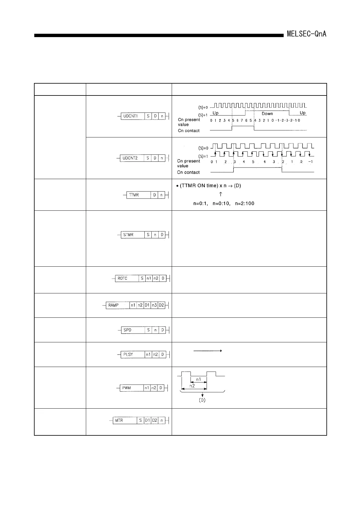
(8) Other convenient instructions
Classification Symbol Description
Up/down counter
Teaching timer
Special timer
• Four bit devices starting with the bit device specified at (D) perform
the following operations in accordance with the ON/OFF status of the
STMR instruction.
(D) + 0: Off delay timer output
(D) + 1: One shot timer output after OFF
(D) + 2: One shot timer output after ON
(D) + 3: On delay timer
Shortest path control
• Rotates a rotary table that is partitioned into n1 from the position at
which it is stopped to the position specified by (S+1) in the direction
that gives the shortest path.
Ramp signal
• Changes the device data specified at (D1) in the range of n1 to n2 in
n3 scans.
Pulse density
• Counts the pulse input of the device specified at (S) for the time
specified at n and stores the result in the device specifid at (D).
Pulse output
•(n1)Hz (D)
Pulse width
modulation
Matrix input
• Consecutively reads the data of n rows of 16 devices starting from
the device specified at (S1) and stores it in devices starting from the
device specified at (D2).
Outputs "n2" times.
 Loading...

