5 - 3
5. I/O NUMBER ASSIGNMENT
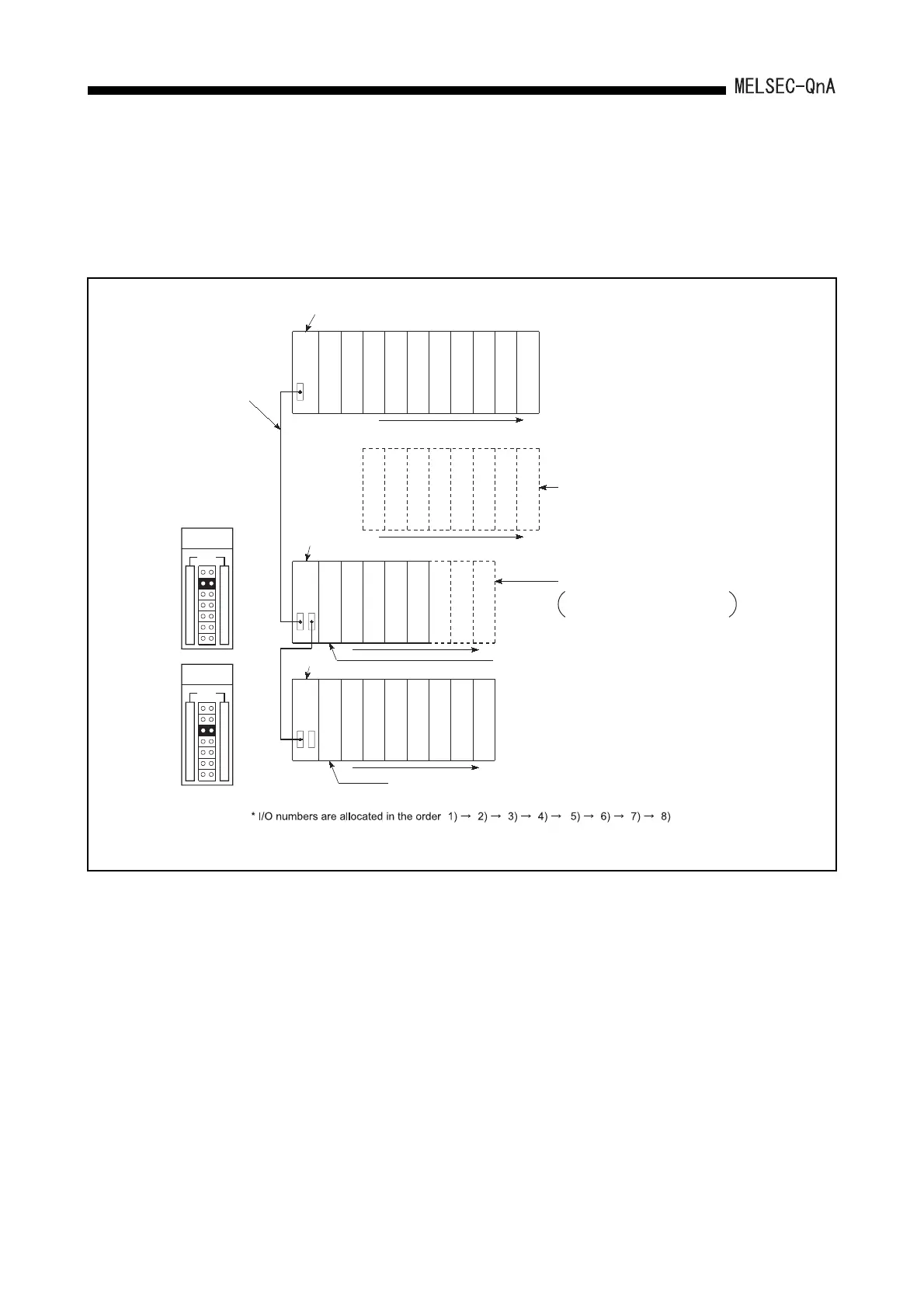
(6) I/O numbers are assigned assuming that every base unit has 8 slots.
If a 5-slot type base unit is used, an I/O number obtained by adding points equivalent
to 3 slots (48 points) to the final I/O number of the 5-slot base unit is assigned to the
next extension base unit.
I/O number assignment example without no extension base on the 1st extension stage
CPU module
Power supply
module
00
0F
10
1F
20
2F
30
3F
40
4F
50
5F
60
6F
70
7F
01234
5
6
7
1) 2)
I/O No. assignment order
80
8F
90
9F
A0
AF
B0
BF
C0
CF
D0
DF
E0
EF
F0
FF
8 9 10 11 12 13 14 15
3) 4)
120
12F
130
13F
140
14F
150
15F
160
16F
170
17F
18 19 20 21
22 23
5) 6)
110
11F
100
10F
1716
1A0
1AF
1B0
1BF
1C0
1CF
1D0
1DF
1E0
1EF
1F0
1FF
26 27 28 29 30 31
7) 8)
190
19F
180
18F
2524
UNIT
1
2
3
4
5
6
7
1
2
3
4
5
6
7
Extension
base unit
Main base unit
Extension
base unit
Stage number setting
Extension cable
UNIT
1
2
3
4
5
6
7
1
2
3
4
5
6
7
8 slots are occupied
Equivalent of 8 slots occupied, allocated as 8 slots.
The three slots, from 21 to 23,
are treated as empty slots.
Number obtained by adding the points of slots 21 to 23 of the previous stage
(48 points) is allocated here.
Example above shows a case where all slots are 16-point modules.
2nd extension
stage
3rd extension
stage
Number obtained by adding equivalent of one extension stage
(128 points) is allocated here.
to to to to to to
to
to to to to to to to to
to to to to to to to to
to to to to to to to to
to
.
 Loading...

