Contents
ii
Page
3.4 Outside dimensions/Installation dimensions .............................................................................................................. 3-41
3.4.1 Outside dimensions ....................................................................................................................................................... 3-41
(1) CR750 controller ....................................................................................................................................................... 3-41
(2) CR751 controller ....................................................................................................................................................... 3-42
3.4.2 Installation dimensions ................................................................................................................................................. 3-43
(1) CR750 controller ....................................................................................................................................................... 3-43
(2) CR751 controller ....................................................................................................................................................... 3-45
3.5 External input/output .......................................................................................................................................................... 3-47
3.5.1 Types .................................................................................................................................................................................. 3-47
3.6 Dedicated input/output ...................................................................................................................................................... 3-48
3.7 Emergency stop input and output etc. ......................................................................................................................... 3-51
3.7.1 Connection of the external emergency stop ...................................................................................................... 3-51
(1) CR750 controller ....................................................................................................................................................... 3-53
(2) CR751 controller ....................................................................................................................................................... 3-57
3.7.2 Special stop input (SKIP) ........................................................................................................................................... 3-60
(1) CR750 controller ....................................................................................................................................................... 3-60
(2) CR751 controller ....................................................................................................................................................... 3-61
3.7.3 Door switch function .................................................................................................................................................... 3-62
3.7.4 Enabling device function ............................................................................................................................................. 3-62
(1) When door is opening ............................................................................................................................................... 3-62
(2) When door is closing ................................................................................................................................................ 3-63
(3) Automatic Operation/Jog Operation/Brake Release and Necessary Switch Settings .............. 3-63
3.8 Mode changeover switch input ........................................................................................................................................ 3-64
(1) Specification of the key switch interface ....................................................................................................... 3-64
(2) Connection of the mode changeover switch input ..................................................................................... 3-65
3.9 Additional Axis Function ..................................................................................................................................................... 3-66
3.9.1 Wiring of the Additional Axis Interface .................................................................................
................................ 3-66
(1) CR750 controller ....................................................................................................................................................... 3-66
(2) CR751 controller ....................................................................................................................................................... 3-67
3.10 Magnet contactor control connector output (AXMC) for addition axes ..................................................... 3-70
(1) CR750 controller ....................................................................................................................................................... 3-70
(2) CR751 controller ....................................................................................................................................................... 3-71
3.11 Options .................................................................................................................................................................................... 3-72
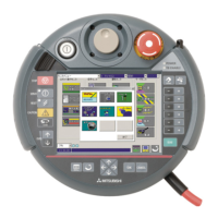
(1) Teaching pendant (T/B) ......................................................................................................................................... 3-73
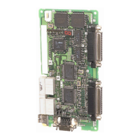
(2) Parallel I/O interface ............................................................................................................................................... 3-76
(3) External I/O cable ..................................................................................................................................................... 3-81
(4) Parallel I/O unit ......................................................................................................................................................... 3-83
(5) External I/O cable ..................................................................................................................................................... 3-94
(6) CC-Link interface ..................................................................................................................................................... 3-96
(7) RT ToolBox2/RT ToolBox2 mini ......................................................................................................................... 3-99
(8) Instruction Manual(bookbinding) ....................................................................................................................... 3-101
3.12 Maintenance parts ........................................................................................................................................................... 3-102
4 Software ......................................................................................................................................................................................... 4-103
4.1 List of commands ............................................................................................................................................................... 4-103
4.2 List of parameters .............................................................................................................................................................. 4-106
5 Instruction Manual ..................................................................................................................................................................... 5-108
5.1 The details of each instruction manuals ................................................................................................................... 5-108
6 Safety .............................................................................................................................................................................................. 6-109
6.1 Safety ...................................................................................................................................................................................... 6-109
6.1.1 Self-diagnosis stop functions ................................................................................................................................ 6-109
6.1.2 External input/output signals that can be used for safety protection measures ........................... 6-110
6.1.3 Precautions for using robot .................................................................................................................................... 6-110
6.1.4 Safety measures for automatic operation ........................................................................................................ 6-111
 Loading...
