68 / 174
Service Manual Mitsubishi SQ-Series diesel engines
Version 08/2004
ENGLISH
PISTONS, CONNECTING RODS,
CRANKSHAFT AND CRANKCASE ENGINE MAIN PARTS
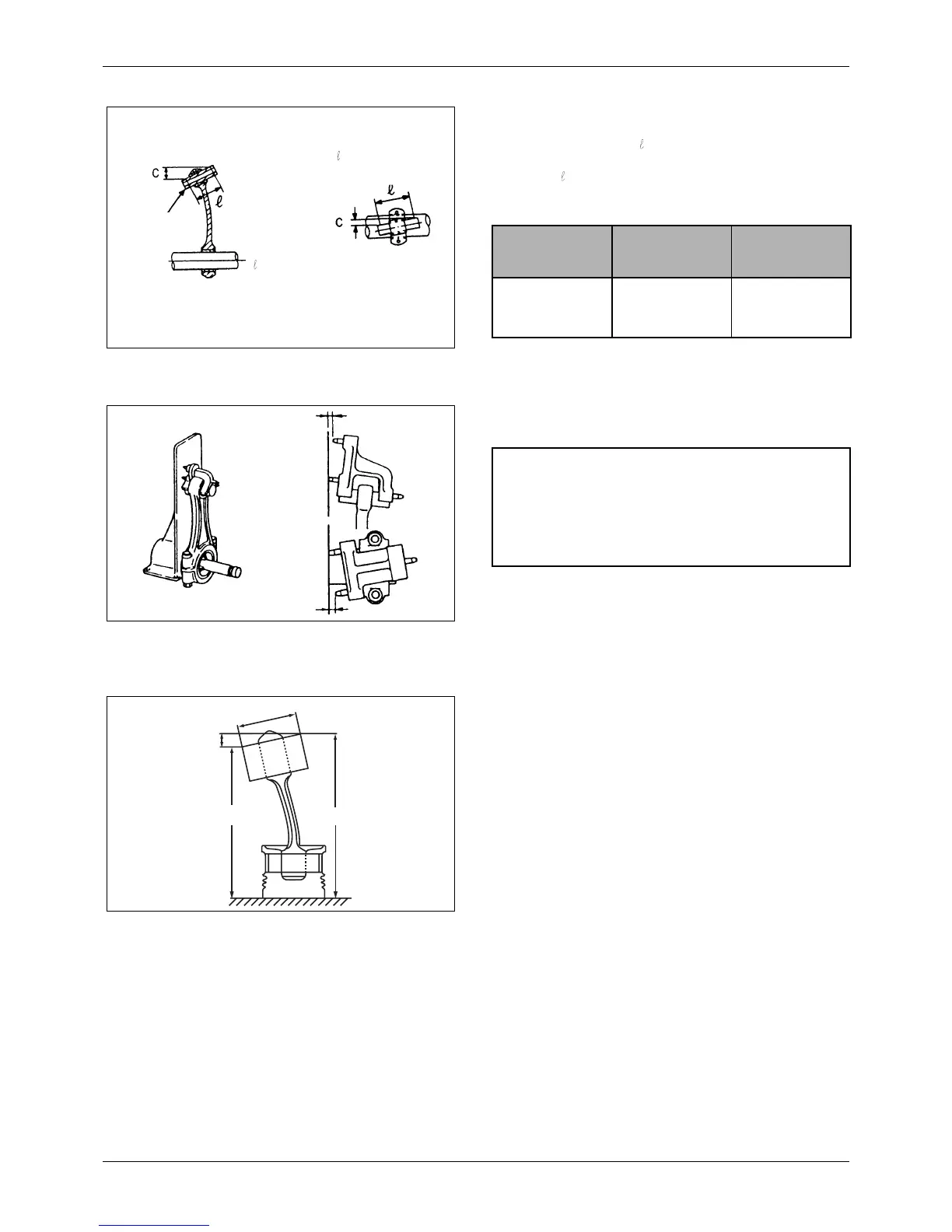
10.2.2 Connecting rods
1. Measure “C” and “ ”. If the measurement at C is
larger than 0.05 mm [0.0020 in.] per 100 mm [3.94
in.] of
, straighten the rod with a press.
Unit: mm (in.)
2. A connecting rod aligner is generally used for
checking the connecting rod for twist and bend.
3. When the measurement is taken with the piston
installed to the connecting rod, place the piston
upside down on a surface plate, insert a round bar
having the same diameter as the crank pin, and
measure the height of the round bar using a dial
gage.
Figure 115 Inspecting connecting rod
Twist
Bend
Piston pin
C
----
0.05 (0.0020)
100 (3.94)
-----------------------------------
<
C
----
0.05 (0.0020)
100 (3.94)
-----------------------------------
<
Unit: mm (in.)
Item Nominal Value
Assembly
Standard
Connecting rod
bend and twist
0.05/100
[0.0020/3.94] or
less
0.15/100
[0.059/3.94]
Figure 116 Checking connecting rod with a
connecting rod aligner
NOTE
To check the connecting rod for bend, install the cap
to the rod and tighten the cap nuts to the specified
torque.
Figure 117 Checking connecting rod with a dial
indicator
AB
C
D

 Loading...


