No. 99MBE011A
ix
3.2.1 Temporarily Fixing the Scale Main Unit ……………………………………………………16
3.2.2 Checking and Adjusting the Parallelism …………………………………………………18
3.2.3 Fully Fixing the Scale Main Unit ……………………………………………………………19
3.3 Mounting the Detector and Adjusting the Position ………………………………20
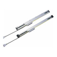
3.3.1 Mounting the Detector ………………………………………………………………………20
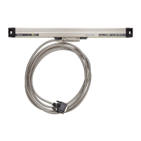
3.4 Connecting and Fixing the Signal Cable …………………………………………22
3.4.1 Connecting the Signal Cable ………………………………………………………………22
3.4.2 Handling the Cables …………………………………………………………………………23
4 Specication ………………………………………………………………………………25
4.1 Specications ………………………………………………………………………25
4.2 Cable Specications …………………………………………………………………26
4.2.1 Signal Cable …………………………………………………………………………………26
4.2.2 One Detector Cable Type …………………………………………………………………27
4.3 DIP Switch Settings …………………………………………………………………28
4.4 Production of Feedback Cable ……………………………………………………29
4.4.1 Appearance Image of Feedback Cable and Grounding to Ground Bar ………………29
4.4.2 Assembly of D-Sub Connector ……………………………………………………………30
4.4.3 Calculation of Feedback Cable Length ……………………………………………………32
4.5 Air Purging ……………………………………………………………………………34
4.5.1 Input Air Specication ………………………………………………………………………34
4.5.2 Air Flow Supplied to the Scale ……………………………………………………………34
4.5.3 Air Supply Unit ………………………………………………………………………………35
4.5.4 Connection Method …………………………………………………………………………37
4.6 External View and Dimensional Drawings of the Scale Main Unit ……………38
4.6.1 Fixing at Multiple Points ……………………………………………………………………38
4.6.2 Fixing at Both Ends …………………………………………………………………………40
5 Troubleshooting …………………………………………………………………………43
6 Appendix …………………………………………………………………………………… 45
6.1 Quantity of the Supplied Accessories for Installation ……………………………45
6.1.1 Fixing at multiple points ……………………………………………………………………45
6.1.2 Fixing at both ends …………………………………………………………………………46
SERVICE NETWORK …………………………………………………………………… App-1
 Loading...