29
4Specication
No. 99MBE011A
4.4
Production of Feedback Cable
A feedback cable is required (prepared by the user) to connect this product to an NC device or some other
device.
Tips
A feedback cable is unnecessary for the one detector cable type (without connector). Attach a connector speci-
ed by the NC device or some other device you want to connect to the top end (discrete-wire part) of the cable.
For the connection diagram for the one detector cable type, refer to
"4.2.2 One Detector Cable Type" (page
27)
The parts required to make a feedback cable are shown below.
Name Specication
Connector for signal cable
This is supplied with this product (socket contact, 15 pins).
This part is unnecessary for the one detector cable type (without
connector).
Connector for NC device
This is not supplied with this product. Prepare a connector speci-
ed by the NC device you want to connect.
Cable material (recommended)
Model number: A66L-0001-0286
Manufacturer: Hitachi Cable or Oki Electric Cable
• When using any cable other than the above recommended cable, make sure to use a shield cable
with the total amount of the impedance of the power supply line (+5 V and 0 V) to "0.65 Ω or less/
total length".
• Install the signal cable so that cutting oil, chips, etc. do not splatter onto the D-sub connector plug.
The D-sub connector of the signal cable has the scale alarm indicator LED (steady red on alarm).
Wire the cable so that the LED indication can be seen.
• Use the feedback cable at a location where no repeated bending occurs.
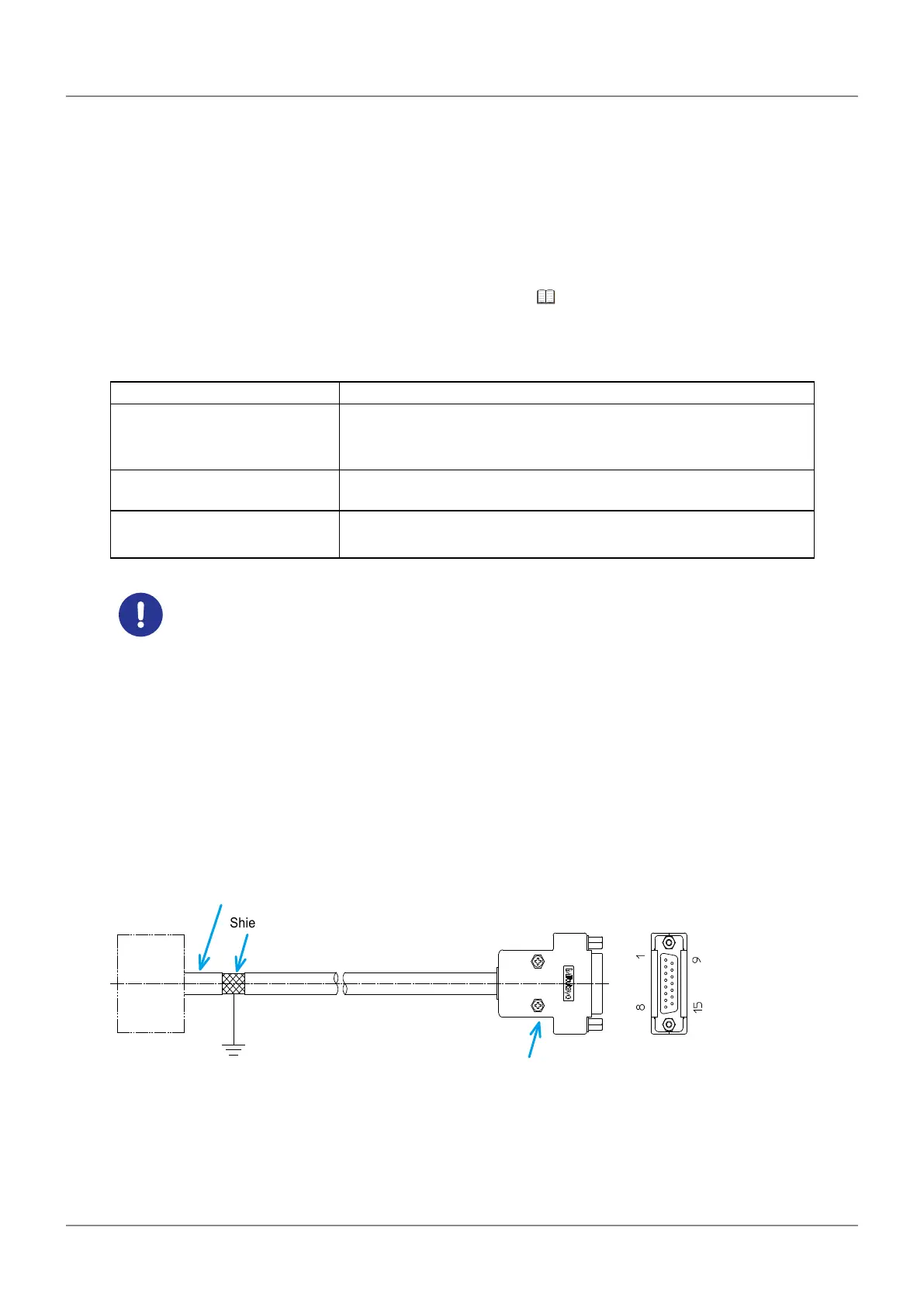
4.4.1 Appearance Image of Feedback Cable and Grounding to
Ground Bar
Connector on the NC device
NC
device
Shielded wire
Output cable
(D-sub connector: socket contact, 15 pins)
Grounding to the ground bar