31
4Specication
No. 99MBE011A
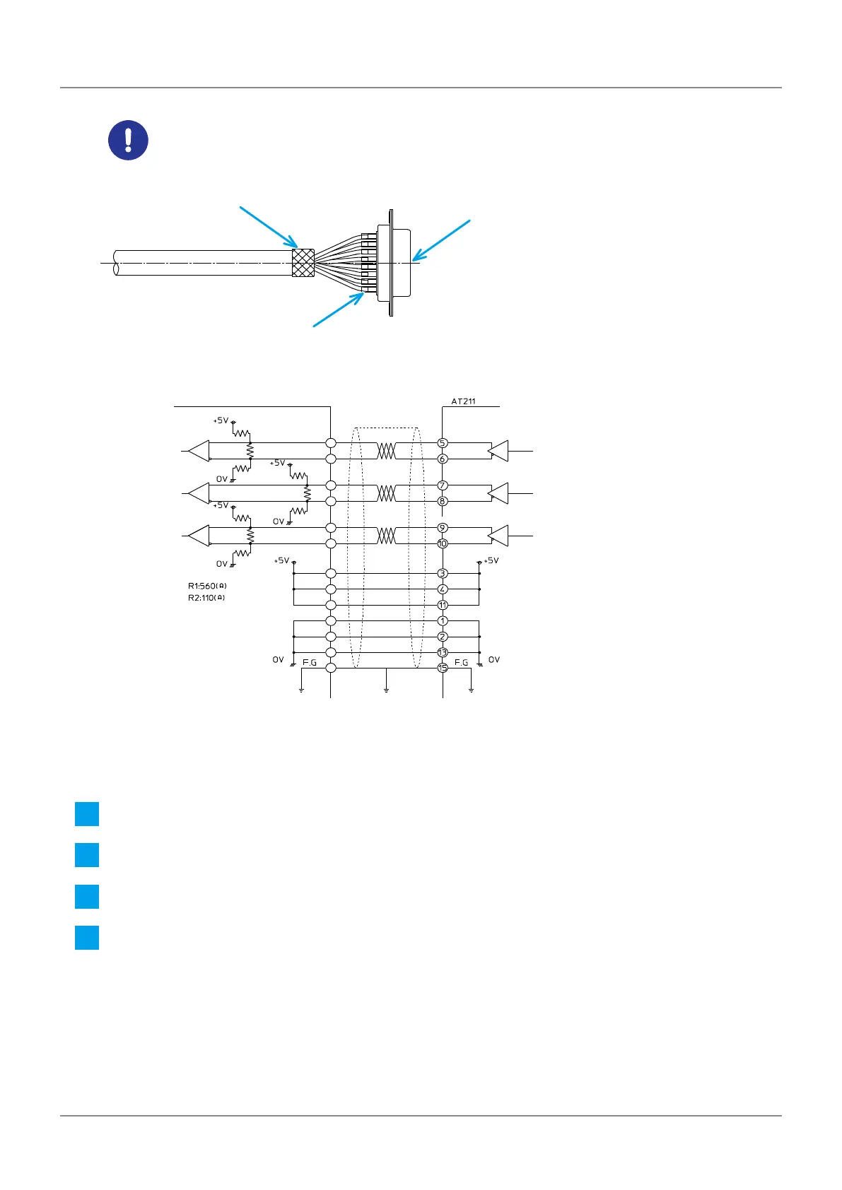
Insert a vinyl tube (ø2 mm, L = 6 mm—8 mm) or heat shrinkable tube into each terminal part.
Bend the shielded wire to the sheath.
D-sub connector
Bending the shielded wire
Vinyl tube (or heat shrinkable tube)
Tips
Line receiver
A-phase
B-phase
Z-phase
B-phase
Z-phase
Control unit etc.
Feedback cable
AM26C31 : TI
AM26C32 :
R2
R2
R1
R2
R2
R1
R2
R2
R1
TI
A-phase
Line driver
• For power: 0.5 mm
2
, three black wires, three red wires
• For signal: 0.18 mm
2
, black x red, black x white, red x white (twisted wire)
• If the shield has a drain wire, connect it to the 15th pin.
5
Set the connector on the plug case (supplied accessory).
6
Screw the shielded wire folded back at step 4 with a cable clamp material (supplied accessory).
7
Set the hex nuts (supplied accessory) in the plug case.
8
Insert the hexagonal joint stand (supplied accessory) from the connector and tighten the screws (tem-
porary xing).