33
4Specication
No. 99MBE011A
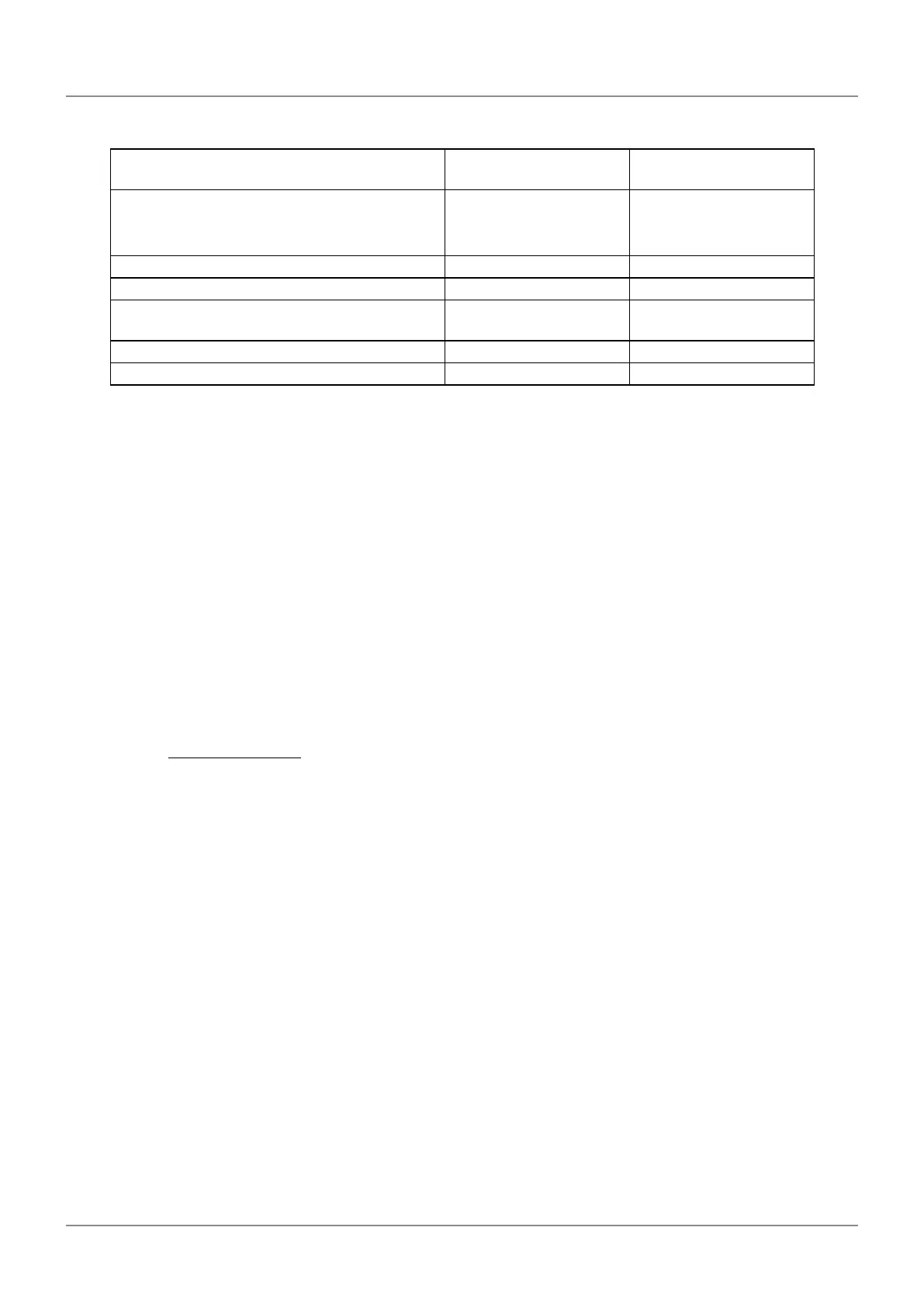
Condition: When the signal cable length is 1 m
Name Specicationsand
symbols
Unit
Maximum cable length
(detector cable length + signal cable length +
feedback cable length)
L m
Wire resistance of used wire material a Ω/m
Number of pairs used for power supply line b Wires
Supply voltage (minimum value) from the NC
device
4.95
*1
V
Current consumption value 0.2 A
Relay connector unit voltage (minimum value) 4.5 + 0.035
*2, *3
V
*1 It is usually the standard supply voltage of the NC device.
*2 When the detector cable length + signal cable length is 1 m or more, a voltage drop of 0.035 V per
1 m occurs.
Consider the voltage drop in the detector cable + signal cable.
*3 Conrm that the input voltage of the relay connector unit is the minimum value or more in the table
above.
Calculation formula
Allowable voltage drop ≥ (Current consumption x wire material resistance x 2 x max cable length) ÷
Number of pairs used for power supply line (1)
Applying the conditions in the above table to formula (1) gives the following result.
(4.95 - (4.5 + 0.035)) [V] ≧ (0.2 [A] x a [Ω/m] x 2 x L [m]) ÷ b [wires] (2)
Modify formula (2) above to the following one.
L [m] ≦
b ( 4.95 - 4.535 )
0.4 a
(3)
Produce the feedback cable of the max cable length (L[m]), wire resistance of used wire material
(a[Ω/m]) and number of pairs used for power supply line (b[wires]) satisfying formula (3) above.