41
4Specication
No. 99MBE011A
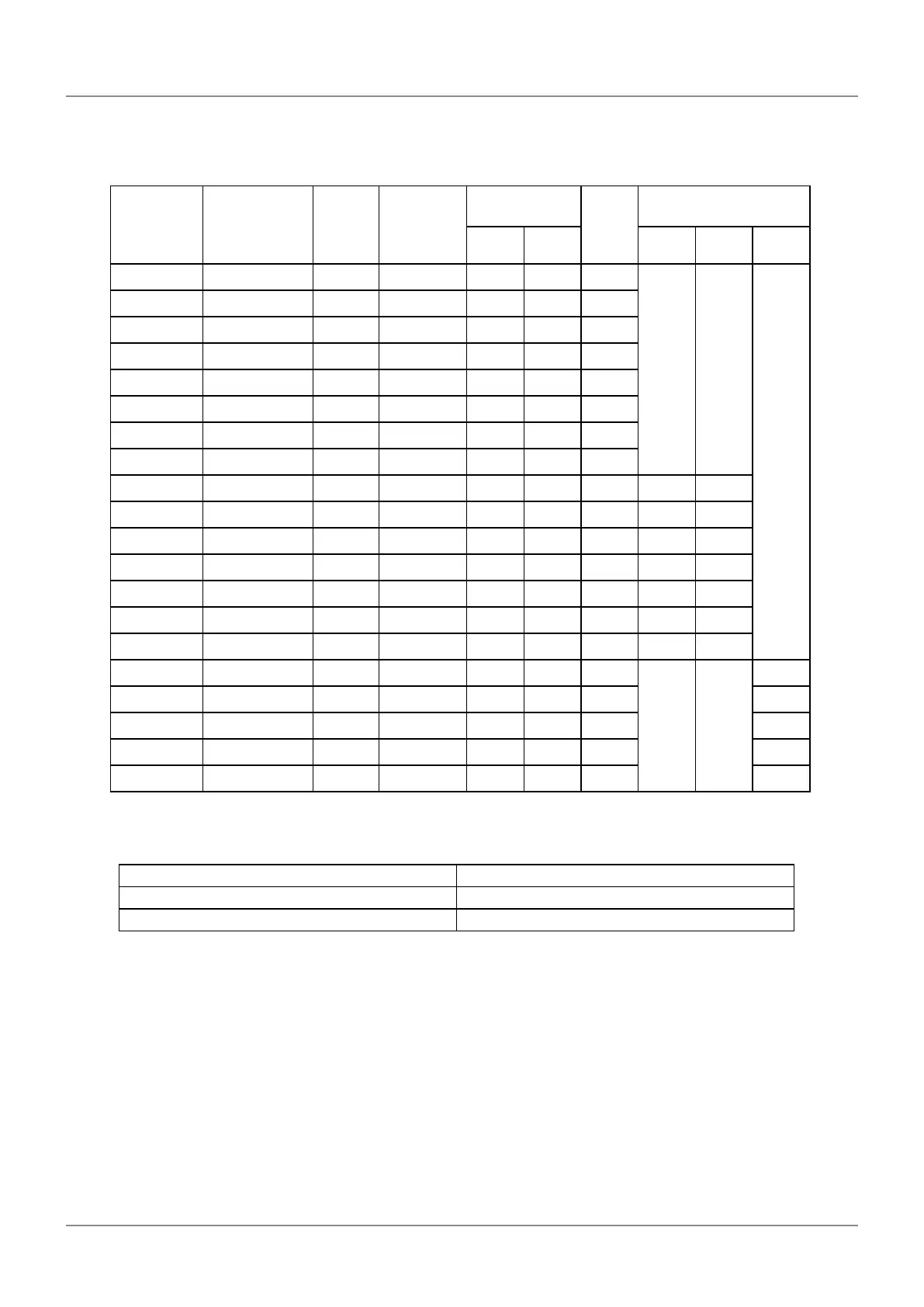
Dimensional drawings table
Unit: mm
Code No. Model No.
Eec-
tive
length
L
0
Maximum
travel dis-
tance L
1
Mounting
hole pitch
Full
length
L
4
Intermediate support
L
2
L
3
L
5
L
6
L
7
539-701B AT211-100B 100 120 258 242 276
- -
-
539-702B AT211-150B 150 170 308 292 326
539-703B AT211-200B 200 220 358 342 376
539-704B AT211-250B 250 270 408 392 426
539-705B AT211-300B 300 330 468 452 486
539-706B AT211-350B 350 380 518 502 536
539-707B AT211- 400B 400 430 568 552 586
539-708B AT211- 450B 450 480 618 602 636
539-709B AT211-500B 500 540 678 662 696 339 331
539-711B AT211- 600B 600 640 778 762 796 389 381
539-713B AT211-700B 700 740 878 862 896 439 431
539-714B AT211-750B 750 780 918 902 936 459 451
539-715B AT211-800B 800 840 978 962 996 489 481
539-716B AT211-900B 900 940 1078 1062 1096 539 531
539-717B AT211-1000B 1000 1040 1178 1162 1196 589 581
539-718B AT211-1100B 1100 1140 1278 1262 1296
- -
430
539-719B AT211-1200B 1200 1240 1378 1362 1396 460
539-720B AT211-1300B 1300 1340 1478 1462 1496 490
539-721B AT211-1400B 1400 1440 1578 1562 1596 530
539-722B AT211-1500B 1500 1540 1678 1662 1696 560
Tips
The number of intermediate supports to be supplied varies depending on the eective length.
Eectivelength(mm) Intermediate support
500 to 1000 A (one location)
1100 to 1500 B, C (two locations)