© MOBATIME 94 / 120 800652.11
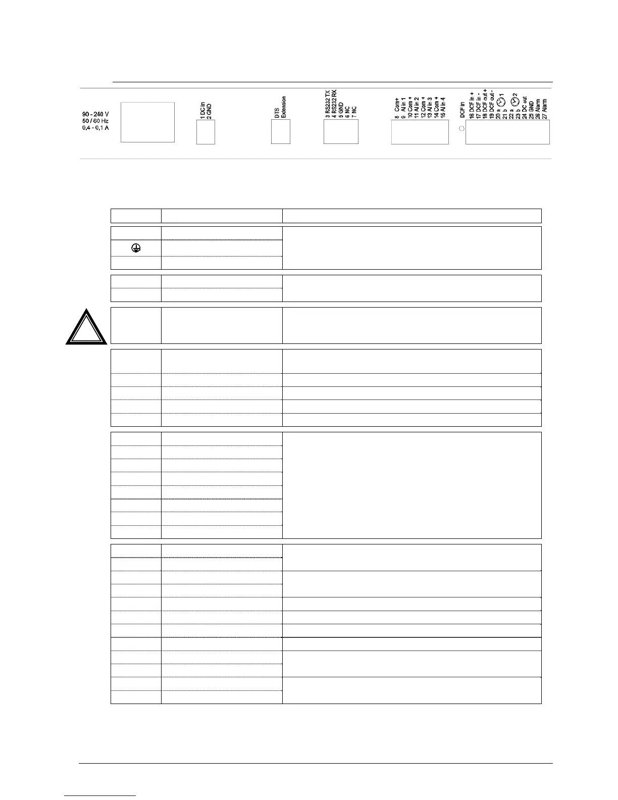
A.3 Connections (rear view) DTS 4802.masterclock
DTS 4802 connections
For technical data see in Appendix “I Technical data“
Clamp Connection Description
L Mains connection phase Mains power input with rubber connector
Break point: by disconnecting the rubber connector
See Appendix I, section "Mains power supply"
Mains connection earth
N Mains connection neutral
1 DC in power supply + Input for external DC supply
Ground
2 DC in power supply GND
DTS Extension
Connection to DTS extension:
Connection length max. 0.5m.
Only plug in connections when the power is off.
3 RS232 TXD
Output for serial telegrams
Connection length max. 30m
4 RS232 RXD* Input for serial telegrams
5 GND
6 NC Not used
7 NC Not used
8 Common + Alarm inputs:
18-36VDC, max. 6mA current consumption, close contact.
Contact closed no alarm.
Length of connection max. 30m.
9 Alarm input 1
10 Common +
11 Alarm input 2
12 Common +
13 Alarm input 3
14 Common +
15 Alarm input 4
16 DCF input +
DCF input e.g. for the connection of a GPS 4500 or DCF
receiver with current loop output.
17 DCF input -
18 DCF output +
DCF or pulse output, current loop passive, Umax=30VDC,
I
on
= 10..15mA, I
off
< 1mA @20VDC
19 DCF output -
20 Slave clock line a 1 Output for MOBALine, impulse line 1 or DCF active line 1
21 Slave clock line b 1 Output for MOBALine, impulse line 1 or DCF active line 1
22 Slave clock line a 2 Output for MOBALine, impulse line 2 or DCF active line 2
23 Slave clock line b 2 Output for MOBALine, impulse line 2 or DCF active line 2
24 DC output + DC output for GPS 4500 or RS 485 slave clocks
28 VDC, max. 400 mA
25 DC output GND
26 Alarm relay Alarm Kontakt, öffnet bei Alarm-
Load: 30 W (60 VDC or 1A) or 60 VA (30 VAC or 1A)
27 Alarm relay
* At the moment only partly available.
!