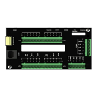
EMC INDUSTRIAL GROUP LTD Dimensions
MW93A_IM_ALL_SV6.09f_en 10/59
Input load 4 kΩ approximate
Digital Inputs INx
High voltage › 8 V
Low voltage ‹ 4 V
Maximum voltage 32 V
Input load 6 kΩapproximate
Input type PNP output sensors
Digital Outputs OUTx
Max output current Σ I
IOx
< 0.25 A
Output voltage same as supply voltage
Communications COM1, COM2 & COM3
COM1 Interface RS232
COM1 Handshake CTS can be enabled
COM2/COM3 Interface RS485
Baud rates 9600, 19200, 38400, 57600, 115200 (230400 on COM2)
Settings 8 data bits, no parity, 2 stop bits (8-N-2)
Protocol Modbus RTU (MWBUS on COM2)
General
IP Rating IP20 (MD1,MP1 facia IP65) (MD2,MP2 facia IP54)
Operating temperature -10 to 45 °C
Supply voltage 10 to 28 Vdc
Power MT1 1.0 to 2.2 W + P
Tacho Excitation
Power MT3 1.0 to 2.2 W + P
Tacho Excitation
Power MR1 1.5 to 2.5 W + P
OUTx
Power MD1 1.8 W
Power MP1 1.8 to 3.0 W
Power MD2 1.4 W
Power MP2 1.4 to 3.1 W
Power MP2 + MO3 3.4 to 5.0 W + P
OUTx
+ P
Tacho Excitation
MP2 Restrictions P
Loadcell Excitation
+ P
AO1
+ P
AO2
< 1.5 W
I
Supply
< 0.5 A
INSTALLATION
The instrumentation must be mechanically installed and then the electrical connections made. The im-
portant electrical connections are as follows.
Power supply connections: 24Vdc fused or current limited to 5A.
Communications: A shielded cable is recommended to connect units together with COM2. It can extend
up to 500m. This leaves COM1 (RS232) free for other applications. For a cable length over 50m, MAT
line terminators must be fitted at each end of the cable.
Loadcell connections: For cable runs less than 20m, a 4 wire connection should be adequate. For longer
cable lengths, a 6 wire connection is recommended.
The ‘material feed’ output to control filling of the weigh hopper.
Speed demand signal (4-20mA) wired to motor speed controller with shielded cable.
If the control feeder motor run/stop is controlled remotely (by PLC etc), then the ModWeigh RUN input
must be connected. It must be ON when the weigh belt motor is running. In this case the START key
on the MD1,MD2 display should be disabled when the system is commissioned.
If the feeder motor run/stop is to be controlled by the ModWeigh instrument, the ModWeigh RUN
MOTOR output should be used to control the feeder motor.
Some additional optional connections are as follows.
A remote totaliser.
The 4-20mA measured flowrate output.
The 4-20mA flowrate setpoint input.
Dimensions
Following are the dimensions of the hardware items that make up the system.
The displays/processors are designed for panel mounting.