EMC INDUSTRIAL GROUP LTD Connections
MW93A_IM_ALL_SV6.09f_en 17/59
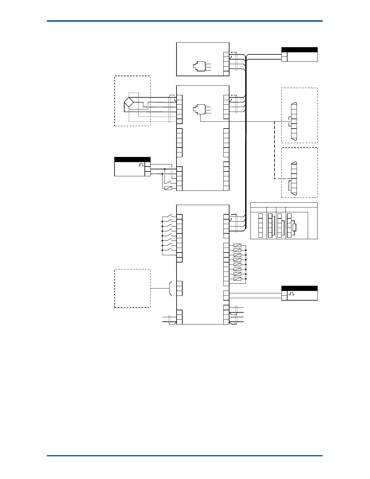
Connection Diagram – MT1
pulse output
material feed
run motor
healthy
weight fault
low flow fault
not filling or discharging
alarm alert
L1
7
8
6
7
20
DB9F
DB25M
PC, PLC
or
ModWeigh Display
MD1,MD2
weight
flowrate
speed demand
hold control
acquire zero
run
reset total
print
print total
run
pause
optional sense for 6 wire
connection
1
1
1
1
2k2
4k7
10k
22k
47k
100k
5
6
7
8
9
10
J1
J2
R1
R2
R3
R4
R5
S4
S5
S6
acquire zero
run motor
Keep all wiring separated
from mains wiring.
Use shielded cable where
indicated.
Either the RUN input or the
RUN MOTOR output should
be used.
For individual loadcell sensi-
tivity adjustment, use termi-
nals P, Q, R and S.
Display and transmitter can
alternatively be connected
COM1 to COM1 using an MAC
cable.
MT1 bus address set with
ADS pin or a setting.
MR1 bus address set with
ADS pin and must be same
as MT1.
Fit an MAT terminator to
each end of COM2 cable if
length exceeds 50m.