EMC INDUSTRIAL GROUP LTD Internal Signals
MW93A_IM_ALL_SV6.09f_en 36/59
Q2337 flowrate filter [0s, 0.5s, 0.7s, 1s, 1.4s, 2s, 3s, 5s, 7s, 10s, 14s,
20s, 30s, 50s]
8308, g6 0
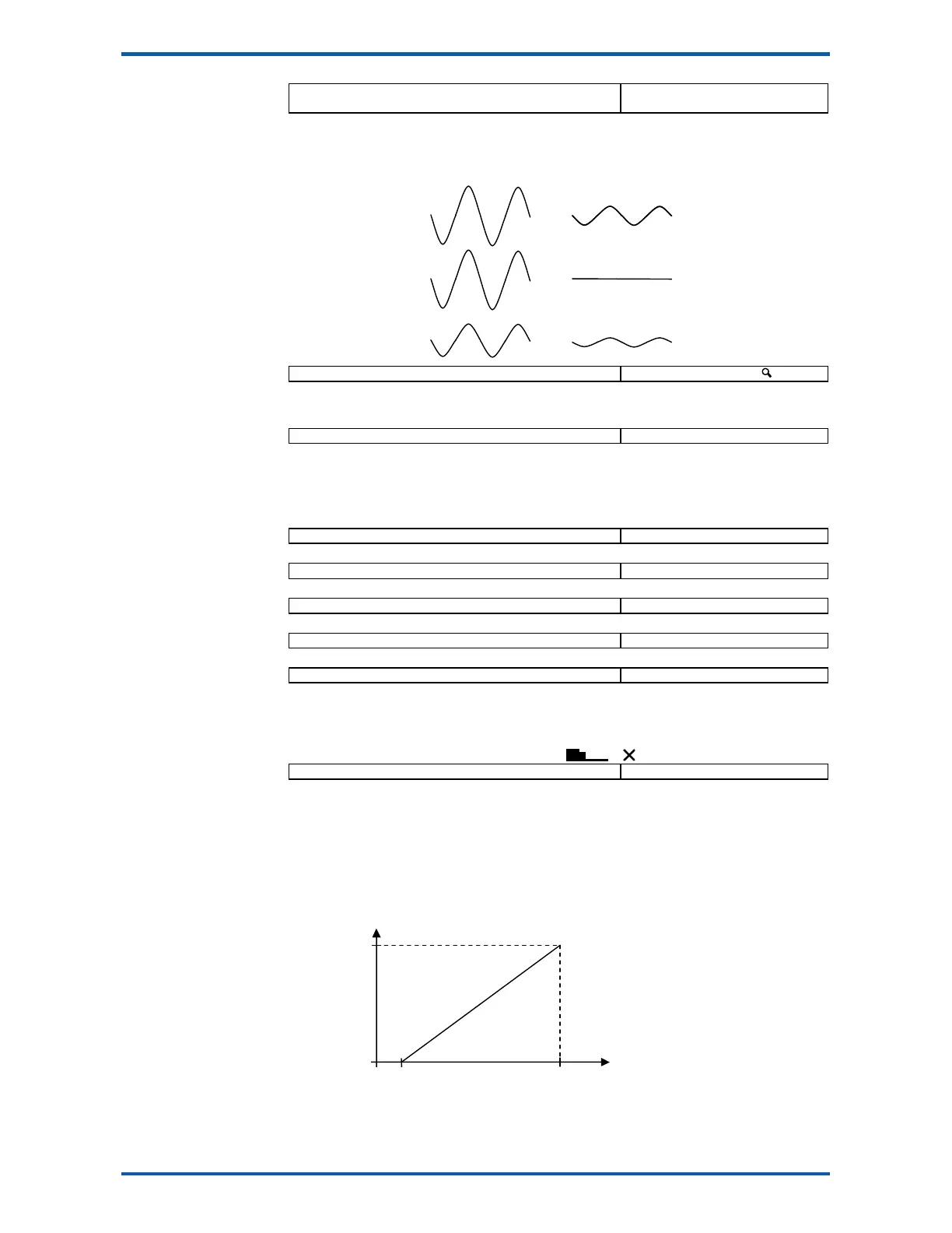
Additional flowrate filtering. Does not affect the control loop settings.
Averages out fluctuations in the flowrate. The amount of filtering does not depend on the signal ampli-
tude. See diagrams following.
Q2338 flowrate raw 8764, g6 t/h,kg/h
The flowrate before the dynamic filter and flowrate filter.
Totaliser
Q2341 low flow cutout 8310 2.0 %
Totalising stops when the flowrate is less than this value.
If a negative value is used, then the low flow cut out occurs within a band. For example, with a setting
of -2%, totalising will stop when the flowrate is between -2% and +2%.
The displayed flowrate is zeroed when the measured flowrate is below the low flow cutout and the con-
troller is stopped.
Q2342 totaliser division 8312 0.05 kg,t,g
Set the resolution of the totaliser.
Q2343 pulse output division 8314 0.05 kg,t,g
Set the resolution of the external totaliser.
Q2344 total weight 8730 0.00 TU
Displays the weight totaliser. The total is retained after a power failure.
Q2345 running total 8732, g6 0.00 TU
Displays a running weight total. This total is not reset by the RESET TOTAL operation.
Q2346 totaliser digits 8320, g6 6
Sets the number of digits the totaliser counts to.
Increasing the number of digits requires more space and the display may become cramped. More
room can be made, for example by removing the material feed stopped icon. This can be done by
setting the ‘secondary line options’ (QK 25643) to 4. To remove the speed demand bar graph and
icons as well, set the ‘secondary line options’ to 12. ( & )
Q2349 running time 8728, g6 h
The total time the system has been running. Accumulates anytime the ‘low flow cutout’ is off.
Adjust motor calibration
The MW93 typically controls a motor speed controller and motor which drives a material feed screw.
The motor speed controller must be set up so that it produces a linear change in screw speed over the
range.
It is recommended that the zero point be adjusted with a speed demand value of 2%.
1. Press START or start the motor externally so that the running light above the START key is
on.
Motor Speed
Just Stopped
speed demand signal
100%
20mA
0%
4mA
before filter
flowrate filter