EMC INDUSTRIAL GROUP LTD Other display settings
MW93A_IM_ALL_SV6.09f_en 52/59
Other display settings
Q97 language select 8618
Selects the language to use for the display.
To change the language in the identification line of the display (top line), reset the ‘system name de-
sign’. When at this setting, press Fn 1 to reset. (Q25541).
When a non-English language is selected, pressing the language key will toggle between the language
and English.
Q98 display brightness 8516
Adjusts the display brightness.
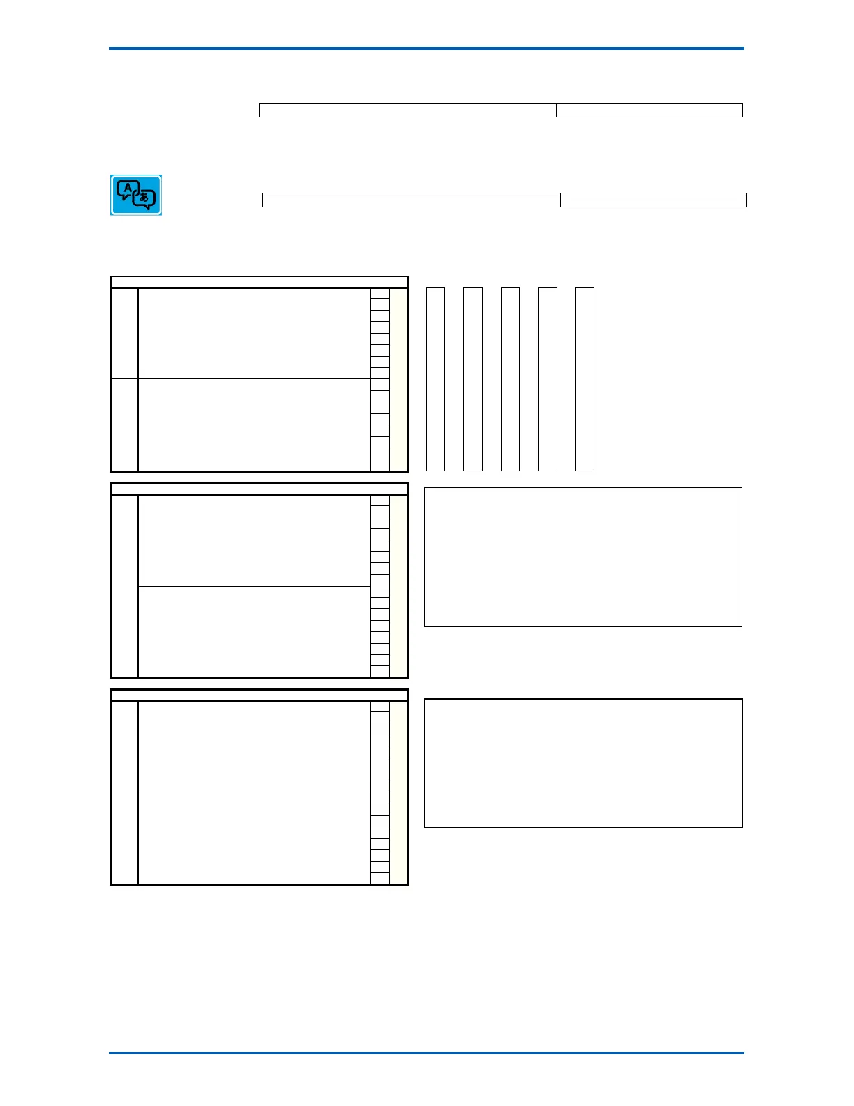
I/O Function Table
Input Functions (level sensitive Π)
0
no function/pulse input †
0 0 208
224
1 stop 1 Ϯ
2 run 2 Ϯ
3 pause 3 Ϯ
4 4 Ϯ
5 volumetric mode 5 Ϯ
6 * remote flowrate mode 6 Ϯ
7 7 Ϯ
8 hold flowrate 8 Ϯ
9 hold control 9 Ϯ
10 feed disable 10 Ϯ
11 11 Ϯ
12 timer enable 12 Ϯ
13 13 Ϯ
14 user bit 1 14 Ϯ
control1_internal
control1C
control1G
control1_inputs_aux
15 user bit 2 15 Ϯ
Control1
=
control1_inputs
or
15
or
223
or
239
or
Input Functions (edge sensitive )
16 acquire zero 0 Ϯ
17 1 Ϯ
18 2 Ϯ
19 3 Ϯ
20 4 Ϯ
21 set volumetric mode 5 Ϯ
22 reset volumetric mode 6 Ϯ
23 volumetric/gravimetric 7 Ϯ
24 set remote mode 8 Ϯ
25 reset remote mode 9 Ϯ
26 remote/local 10 Ϯ
27 start 11 Ϯ
28 timer start 12 Ϯ
29 start key 13 Ϯ
30 pause key 14 Ϯ
31 stop key 15 Ϯ
Control2
Input Functions (edge sensitive )
32 reset total 0 Ϯ
33 totalise 1 Ϯ
34 2 Ϯ
35 start2 key 3 Ϯ
36 stop2 key 4 Ϯ
37 user function 1 5 Ϯ
38 user function 2 6 Ϯ
39 user function 3 7 Ϯ
40 print 8 Ϯ
41 print total 9 Ϯ
42 print remote 10 Ϯ
43 print total remote 11 Ϯ
44 12 Ϯ
45 acknowledge alarms 13 Ϯ
46 14 Ϯ
47 capture weight 15 Ϯ
Conotrol3
CONTROL1
The control1 register contains 16 level sensitive input signals. This register has 5
control sources which are combined together.
control1_inputs come from the digital inputs as set with the ‘INx functions’.
control1_internal are internally generated signals (e.g. the START/STOP keys).
control1C and control1G are registers accessible via communications and are for
remote control of the instrument.
control1_input_aux come from auxiliary IO
The 4 registers are or’ed together, so for example a 1 on bit 2 of any of the 4
sources will set the run bit. Any control1 register with bit 1 set (stop) will override
and cause a stop.
To invert signal, use negative value.
e.g. for NOT run, use -2.
† IN0 is pulse input, other inputs are no function.
‡ Only OUT0 & OUT1 maybe set to pulse output. Other outputs are no function.
Ϯ can be set and reset with macros and the setting IO Control (Q25420)
* retained while power is off