EMC INDUSTRIAL GROUP LTD Setup
MW94A_IM_ALL_SV6.09f_en 18/53
SETUP
Basic Settings
AI1 AO1
AI2 AO2
IN1 OUT1
IN2 OUT2
IN3 OUT3
IN4 OUT4
IN5 OUT5
IN6 OUT6
IN7 OUT7
IN8
Inputs
Internal Signals
Outputs
OUT8
COM1
Communications & Display
COM2
Information, Resets & Final Calibration
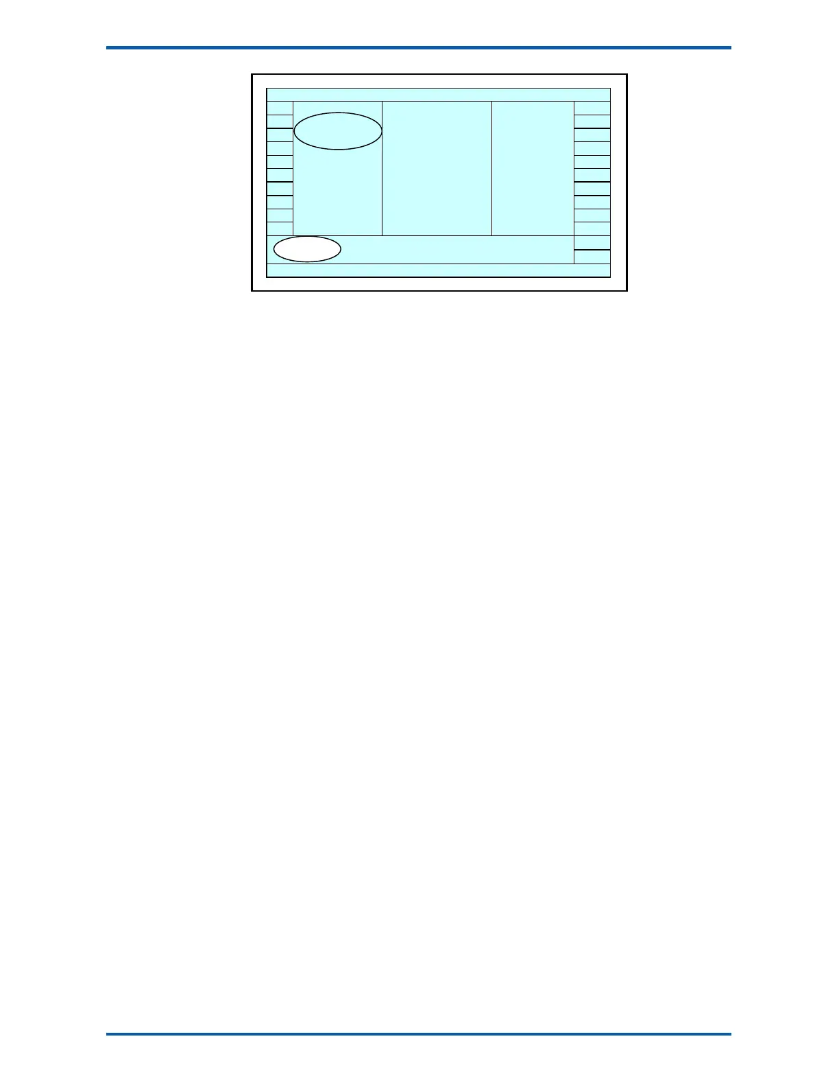
Setup Diagram
The Setup contains
Settings
and
Macros
which are described next.
Settings
Most of the setup for a system involves setting calibration constants which for example calibrate the
loadcell input, the 4-20mA outputs and the operation of relays etc. These settings are simple numeric
values.
Macros
Macros are used to store short programs which are used to construct text strings to output to the
printer, perform arithmetic calculations and other special control functions. Macros are a collection of
program segments which can call one another as subroutines. They have structured if/then/else state-
ments and program looping constructs.
A macro is a sequence of numbers (bytes with values of 0 to 255).
Menus
All the setup parameters are contained within a menu structure which follows the setup sections.
Basic Settings
Inputs
Internal Signals
Outputs
Communications & Display
Information, Resets & Final Calibration
Factory Settings
Basic Settings
The basic settings are settings which generally must be set first and often affect other settings through
the controller. For example, they set the engineering units and measuring range for the application.
Inputs
The inputs are settings and calibration which effect the basic inputs signals. For example the loadcell
input, tacho input (where used) and digital inputs.
Internal Signals
This section contains the main calculations for the instrument. Most signals are here, for example the
weight, zero weight, total weight etc. Much of the instruments configuration is done in this section.
Outputs
The output are settings and calibration which effect the basic output signals. For example the 4-20mA
outputs and digital outputs. These change the calibration range and select the signal to appear on the
digital outputs.
Communications & Display
This section sets the baud rates etc for the communications ports. It sets the key locks for the
MD1,MD2 Display. It also contains the Macros for the instrument.
These settings are not available in ‘B’ model instruments.
Information, Resets & Final Calibration
This section contains information about the unit, including its serial number, the product type etc.
These settings allow all the settings & macros to be reset back to their default values. The final calibra-
tion is also done here.
Factory Settings
The factory settings are used to calibrate the basic instrument in the factory. These are password pro-
tected and are not usually required once the instrument has left the factory.
Loadcell
Calibration
Macros