EMC INDUSTRIAL GROUP LTD Setup
MW94A_IM_ALL_SV6.09f_en 17/53
A multidrop connection can also be used with any other Modbus master device such as a PLC. If a non
ModWeigh master is used on the bus, then the ModWeigh instruments are unable to communicate with
one another. An external Modbus master can alternatively be connected to an RS232 COM1 port.
An MR1 unit cannot share the bus with a non ModWeigh master such as a PLC. A PLC could be con-
nected using the COM3 port on the MR1.
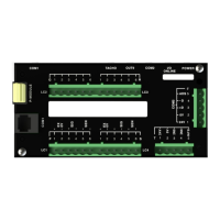
To connect in mutidrop use the RS485 connection COM2. The wiring should be made in a daisy-chain,
with one instrument connected to the next. If a stub connection is used to a main cable as shown in the
diagram, then make sure its length limit is adhered to.
Two MAT line terminators must be fitted, one at each end of the cable run.
The +D, -D and a 0V terminal must all be connected together through the data cable.
Setting the COM1 Modbus Address
Before a multidrop system will operate, the addresses in each of the ModWeigh units will need to be set
differently. This can be done by wiring a link or resistor to the ADS terminal where available. See the
table on the connection diagram. Alternatively the address setting can be changed in each unit using a
display connected to its COM1.
The following procedure is used to set a units address.
1. Press the Q key to access the setup menu.
2. Key in the quick key code 2512 to select the ‘COM1&2 modbus address’ step.
3. Press the EDIT key. (If editing is locked, key in the password 111 and press ENTER).
4. Enter the desired address (1, 2 or 3 etc.) and press ENTER.
5. Press and hold the BACK key to return to normal operation.
6. Repeat for each of the units which are to be used on the bus.
When the multidrop system is then connected and powered, the display should be able to see each of
the ModWeigh systems. This is done by pressing the SELECT key on the display.
SETTING UP
Setup
ModWeigh instruments must be calibrated for each specific application. The parameters stored are col-
lectively known as the Setup.
Description
Press the Q key to access the setup menu.
The setup is divided into sections as shown in the following diagram.
][
40
m
n
Li ≤
][500 mL
if D = MD1,MD2 Display, then n ≤ 10
if D = PLC master, then n ≤ 32