EMC INDUSTRIAL GROUP LTD Dimensions
MW94A_IM_ALL_SV6.09f_en 8/53
Digital Outputs OUTx (except OUT0)
Max output current Σ I
IOx
< 0.25 A
Output voltage same as supply voltage
Communications COM1, COM2 & COM3
COM1 Interface RS232
COM1 Handshake CTS can be enabled
COM2/COM3 Interface RS485
Baud rates 9600, 19200, 38400, 57600, 115200 (230400 on COM2)
Settings 8 data bits, no parity, 2 stop bits (8-N-2)
Protocol Modbus RTU (MWBUS on COM2)
General
IP Rating IP20 (MD1,MP1 facia IP65) (MD2,MP2 facia IP54)
Operating temperature -10 to 45 °C
Supply voltage 10 to 28 Vdc
Power MT1 1.0 to 2.2 W + P
Tacho Excitation
Power MT3 1.0 to 2.2 W + P
Tacho Excitation
Power MR1 1.5 to 2.5 W + P
OUTx
Power MD1 1.8 W
Power MP1 1.8 to 3.0 W
Power MD2 1.4 W
Power MP2 1.4 to 3.1 W
Power MP2 + MO3 3.4 to 5.0 W + P
OUTx
+ P
Tacho Excitation
MP2 Restrictions P
Loadcell Excitation
+ P
AO1
+ P
AO2
< 1.5 W
I
Supply
< 0.5 A
INSTALLATION
The instrumentation must be mechanically installed and then the electrical connections made. The im-
portant electrical connections are as follows.
Power supply connections: 24Vdc fused or current limited to 5A.
Communications: A shielded cable is recommended to connect units together with COM2. It can extend
up to 500m. This leaves COM1 (RS232) free for other applications. For a cable length over 50m, MAT
line terminators must be fitted at each end of the cable.
Loadcell connections: For cable runs less than 20m, a 4 wire connection should be adequate. For longer
cable lengths, a 6 wire connection is recommended.
Some additional optional connections are as follows.
A remote totaliser.
The 4-20mA measured flowrate output.
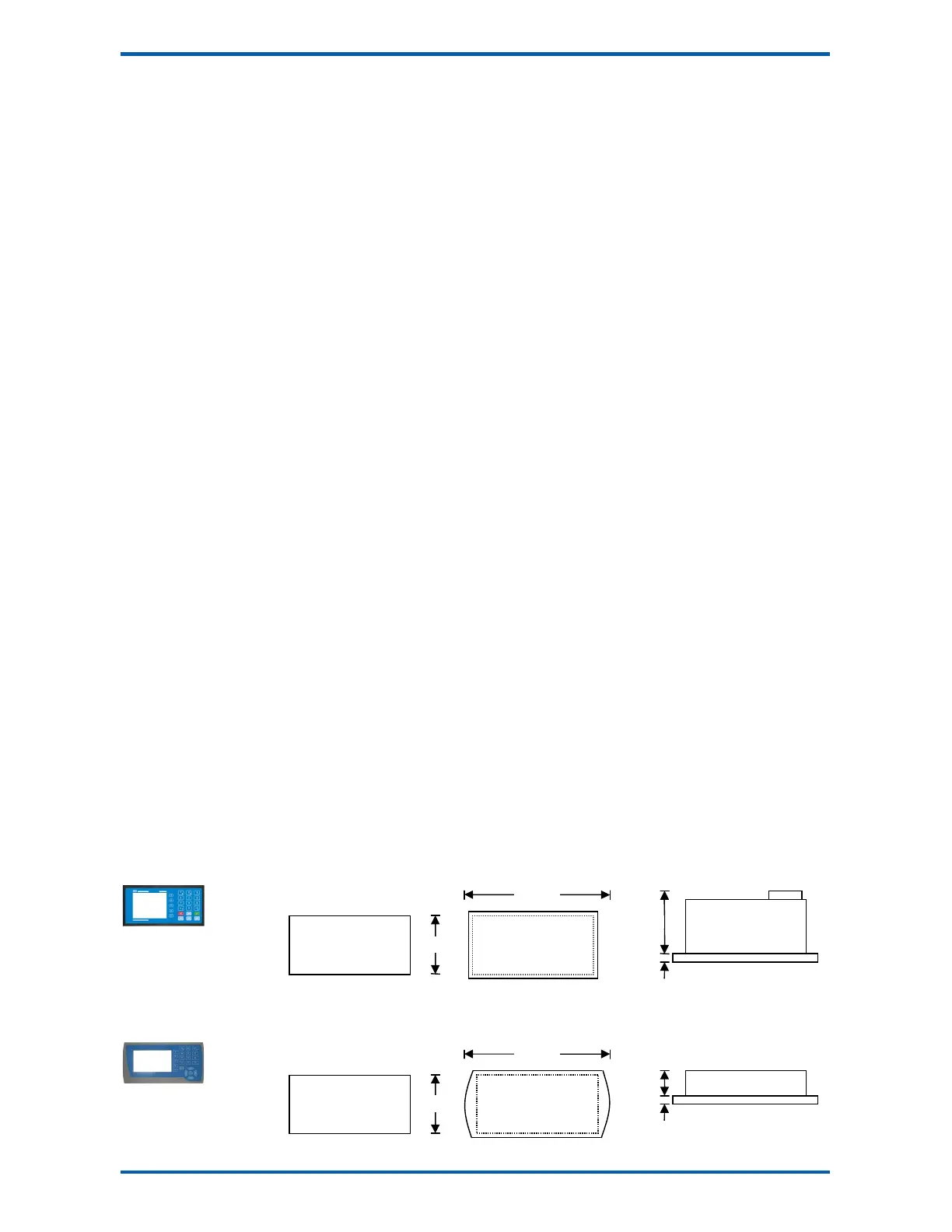
Dimensions
Following are the dimensions of the hardware items that make up the system.
The displays/processors are designed for panel mounting.
MD2 Display
MP2 Processor
MD1 Display
MP1 Processor
PANEL cut out
186 x 92 mm
-0.0 + 1.0 mm
FACIA
208 x 104 mm
top view
approx. 450g
PANEL cut out
138 x 67 mm
-0.0 + 1.0 mm
FACIA
144 x 72 mm
top view
approx. 400g