MONITOR
HEATING
SYSTEM
Section
2:
Installation
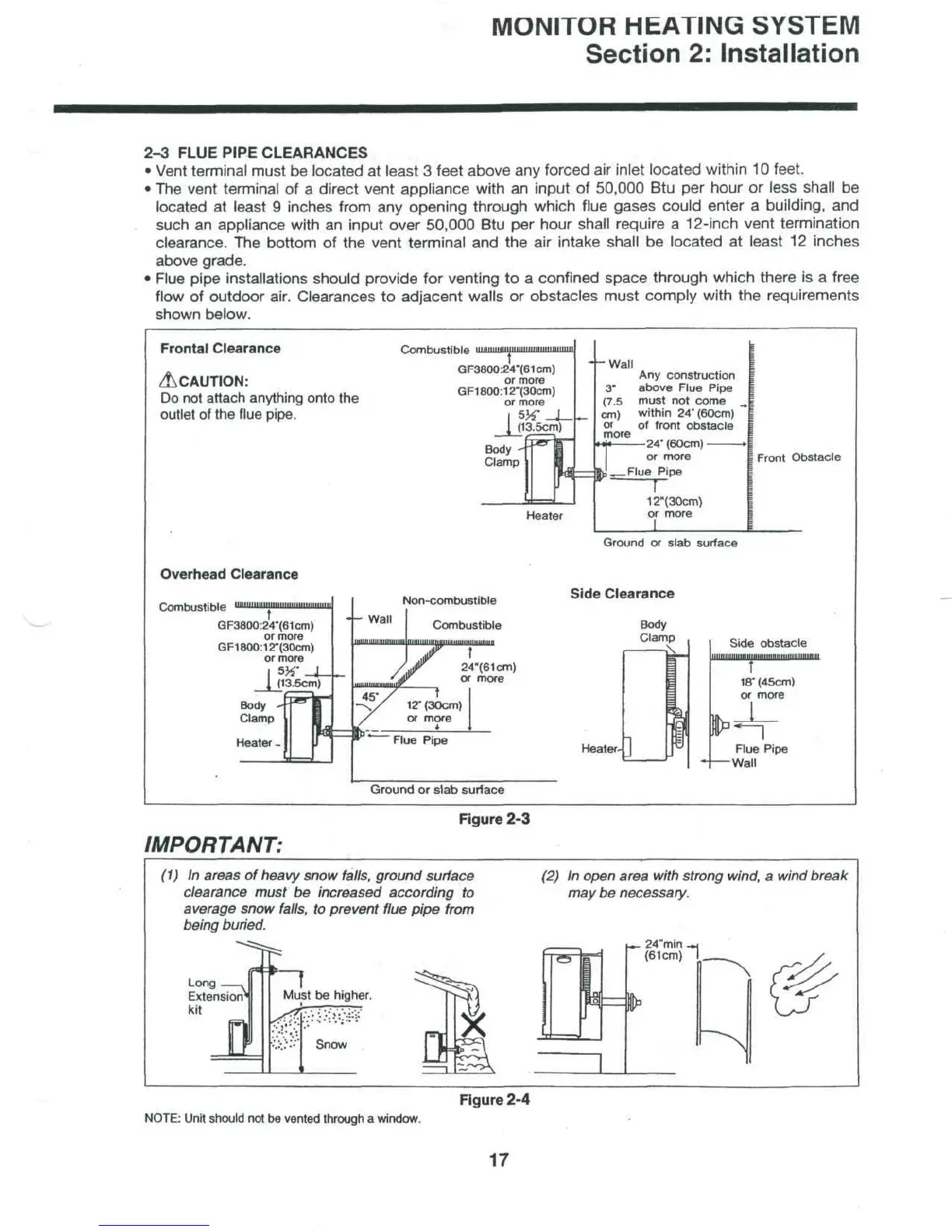
2-3
FLUE
PIPE
CLEARANCES
•
Vent terminal must
be
located
at
least
3
feet
above
any
forced
air
inlet located within
10
feet.
• The
vent terminal
of a
direct vent appliance with
an
input
of
50,000
Btu per
hour
or
less shall
be
located
at
least
9
inches from
any
opening
through which flue gases
could
enter
a
building,
and
such
an
appliance with
an
input over 50,000
Btu per
hour shall require
a
12-inch vent termination
clearance.
The
bottom
of the
vent terminal
and the air
intake shall
be
located
at
least
12
inches
above
grade.
•
Flue pipe installations should provide
for
venting
to a
confined
space through which there
is a
free
flow
of
outdoor air. Clearances
to
adjacent walls
or
obstacles must comply with
the
requirements
shown
below.
Frontal Clearance
&CAUTION:
Do not
attach anything
ontc
outlet
of the
flue
pipe.
Overhead
Clearance
GF3800:24-(61cm)
or
more
GF1800:12'(30cm)
or
more
|
(13.5cm)
Body
-
"
j~
Clamp
M
Heater
-
_
. r
J
GF3800:24-(61cm)
or
more
GF1800:12"(30cm)
or
more
_Jj13.5crn)
Clamp
H
Heater
c
Non-combustible
~
Wal1
Combustible
/Jr
24"(61cfn)
"
msmmifL
v
more
-x/
^2•
(30cm)
/
or
more
1
*
-
Flue
Pipe
Ground
or
slab
surface
- -
Wall
Any
construction
3-
above
Flue
Pipe
(7.5
must
not
come
_
_
cm)
within
24"
(60cm)
or
of
front
obstacle
more
«»[«
—
24'
(60cm)
>
or
more
T^_Flue
Pipe
12"(30cm)
or
more
Ground
or
slab
surface
ide
Clearance
Body
Clamp
Sjd(
CM
Heater-
]
Fli
I " Wa
Front
Obstacle
i
obstacle
r
r
(45cm)
more
L
n
ie
Pipe
II
Figure
2-3
IMPORTANT:
(1) In
areas
of
heavy snow falls, ground surface
clearance must
be
increased according
to
average snow
falls,
to
prevent flue pipe from
being buried.
(2)
In
open area with strong wind,
a
wind break
may
be
necessary.
r
z<»
'min
.-
(61cm)
Long
Extension
kit
1
Must
be
higher.
Snow
Figure
2-4
NOTE:
Unit
should
not be
vented
through
a
window.
17