MONITOR
HEATING SYSTEM
Section
2:
Installation
Instructions
for
Manifold
Pressure Adjust-
ments
[A]
Combustion, Pressure Control
of Gas
Control
Valve
A-1
Preparation
for
Pressure Control
of Gas
Control Valve
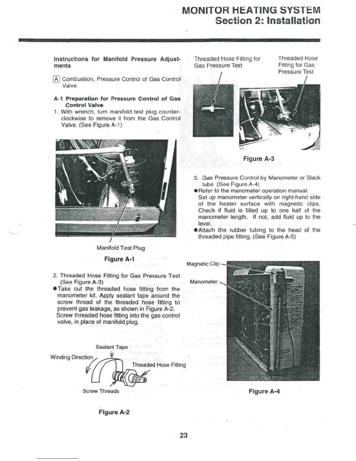
1.
With wrench, turn manifold test plug counter-
clockwise
to
remove
it
from
the Gas
Control
Valve.
(See Figure A-1)
Manifold Test Plug
Figure
A-1
Threaded Hose Fitting
for
Gas
Pressure
Test
Threaded Hose
Fitting
for Gas
Pressure
Test
Figure
A-3
3. Gas
Pressure Control
by
Manometer
or
Slack
tube (See Figure A-4)
•
Refer
to
the
manometer operation manual.
Set
up
manometer vertically
on
right-hand side
of
the
heater surface with magnetic clips.
Check
if
fluid
is
filled
up to one
half
of the
manometer
length.
If
not,
add
fluid
up to the
level.
•Attach
the
rubber tubing
to the
head
of the
threaded pipe fitting. (See Figure A-5)
Magnetic
Clip
2.
Threaded Hose Fitting
for Gas
Pressure Test
(See
Figure
A-3)
•Take
out the
threaded hose fitting from
the
manometer kit. Apply sealant tape around
the
screw
thread
of the
threaded hose fitting
to
prevent
gas
leakage,
as
shown
in
Figure A-2.
Screw
threaded
hose fitting
into
the gas
control
valve,
in
place
of
manifold
plug.
Winding
Direction
Threaded
Hose
Fitting
Screw
Threads
Figure
A-4
Figure
A-2
23