MONITOR
HEATING SYSTEM
Section
2:
Installation
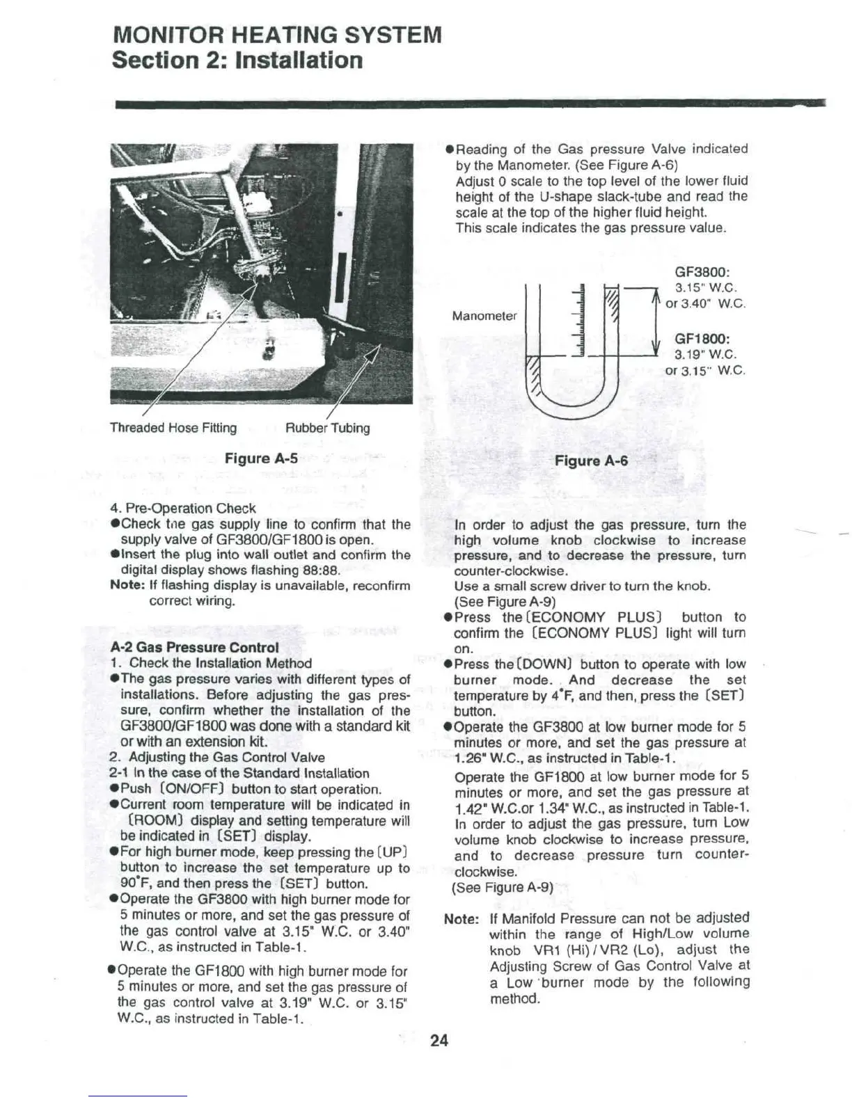
Threaded
Hose
Fitting
Rubber
Tubing
Figure
A-5
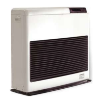
•
Reading
of the Gas
pressure Valve indicated
by
the
Manometer. (See Figure A-6)
Adjust
0
scale
to the top
level
of the
lower fluid
height
of the
U-shape
slack-tube
and
read
the
scale
at the top of the
higher
fluid
height.
This scale indicates
the gas
pressure value.
Manometer
7
1
i
^
GF3800:
3.
15"
W.C.
^
or
3.40" W.C.
,
GF1800:
3.
19"
W.C.
or
3.15" W.C.
Figure
A-6
4.
Pre-Operation Check
•Check
tne
gas
supply
line
to
confirm that
the
supply valve
of
GF3800/GF1800
is
open.
•
Insert
the
plug
into
wall
outlet
and
confirm
the
digital display shows flashing 88:88.
Note:
If
flashing display
is
unavailable, reconfirm
correct
wiring.
:
A-2
Gas
Pressure Control
1.
Check
the
Installation
Method
•The
gas
pressure varies with different types
of
installations.
Before adjusting
the gas
pres-
sure, confirm whether
the
installation
of the
GF3800/GF1800
was
done
with
a
standard
kit
or
with
an
extension
kit.
2.
Adjusting
the Gas
Control
Valve
2-1
In the
case
of the
Standard
Installation
•
Push
[ON/OFF)
button
to
start
operation.
•Current
room temperature will
be
indicated
in
(ROOM]
display
and
setting
temperature
will
be
indicated
in
[SET]
display.
•
For
high burner mode, keep pressing
the
(UP)
button
to
increase
the set
temperature
up to
90°F,
and
then press
the
(SET) button.
•
Operate
the
GF3800 with high burner mode
for
5
minutes
or
more,
and set the gas
pressure
of
the
gas
control valve
at
3.15" W.C.
or
3.40"
W.C.,
as
instructed
in
Table-1.
•
Operate
the
GF1800 with high burner mode
for
5
minutes
or
more,
and set the gas
pressure
of
the
gas
control valve
at
3.19" W.C.
or
3.15"
W.C.,
as
instructed
in
Table-1.
In
order
to
adjust
the gas
pressure, turn
the
high
volume knob clockwise
to
increase
pressure,
and to
decrease
the
pressure,
turn
counter-clockwise.
Use
a
small screw driver
to
turn
the
knob.
(See
Figure
A-9)
•
Press
the
(ECONOMY PLUS) button
to
confirm
the
(ECONOMY PLUS) light will turn
on.
•
Press
the
(DOWN) button
to
operate with
low
burner
mode.
And
decrease
the set
temperature
by
4*F,
and
then,
press
the
(SET)
button.
•Operate
the
GF3800
at low
burner
mode
for 5
minutes
or
more,
and set the gas
pressure
at
1.26" W.C.,
as
instructed
in
Table-1.
Operate
the
GF1800
at low
burner
mode
for 5
minutes
or
more,
and set the gas
pressure
at
1.42" W.C.or 1.34" W.C.,
as
instructed
in
Table-1.
In
order
to
adjust
the gas
pressure, turn
Low
volume knob clockwise
to
increase pressure,
and to
decrease pressure turn counter-
clockwise.
(See
Figure A-9)
Note:
If
Manifold Pressure
can not be
adjusted
within
the
range
of
High/Low volume
knob
VR1
(Hi)/VR2(Lo),
adjust
the
Adjusting
Screw
of Gas
Control Valve
at
a Low
burner mode
by the
following
method.
24