SECTION EIGHT – Safety function RESTART INTERLOCK (Optional)
DS2000 USER’S MANUAL (rev.C)
8.8
8.5 RESTART INTERLOCK CONNECTIONS
The hardware channels of the restart interlock circuit are controlled using the RESTART
INTERLOCK connector.
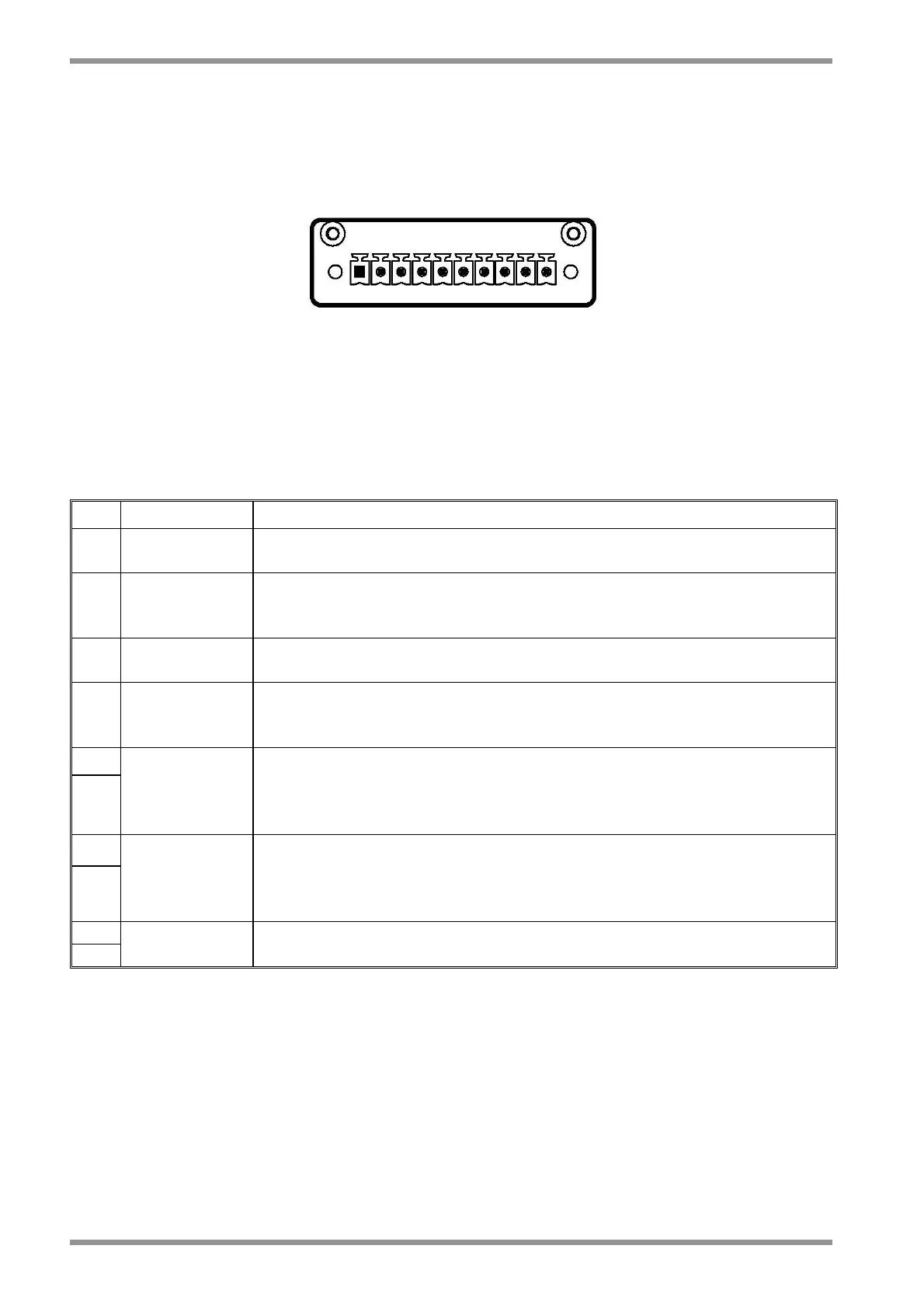
Note: pin 1 is marked with the symbol “■”
Fig.8.2 – Restart Interlock connector, panel side
Tab. 8.1 - RESTART INTERLOCK CONNECTOR
Mating connector: 10 contacts, series MC 1,5/10-STF-3,81 by Phoenix
Pin Name Function
1 - “Channel 1”
Input 0V to bobbin of RL1A Safety Relay of Channel 1 from
door/gate
2 + “Channel 1”
Input to bobbin of RL1A Safety Relay of Channel 1 from door/gate.
With the door closed, this input must be high (+24Vdc). When the
door is opened this input must change to low (0V).
3 - “Channel 2”
Input 0V to bobbin of RL2A Safety Relay of Channel 2 from
door/gate
4 + “Channel 2”
Input to bobbin of RL2A Safety Relay of Channel 2 from door/gate.
With the door closed, this input must be high (+24Vdc). When the
door is opened this input must change to low (0V).
5
6
“Channel 1
verification”
NC contact
NC contact of RL1A Safety Relay of Channel 1. Feedback of RIC.
When closed (high), the Restart Interlock function is active. The
external verification system must monitor this output signal for
plausibility with its input signal
7
8
“Channel 2
verification”
NC contact
NC contact of RL2A Safety Relay of Channel 2. Feedback of RIC.
When closed (high), the Restart Interlock function is active. The
external verification system must monitor this output signal for
plausibility with its input signal
9 NO contact Series of NO contacts of RL1A and RL2A relays. User available.
10
Wiring practice
The external cable to RESTART INTERLOCK connector must be protected against
mechanical damages according to the safety requirements of EN ISO 13849-2:2003, tab.
D.4 (prEN 954-2) in order to prevent short circuits.