SECTION FIVE – COMPONENT DESCRIPTION
DS2000 USER’S MANUAL (rev.C)
5.7
5.4 CONTROL SECTION
The Control section has the following features:
• Speed loop
• Current loop
• Low-pass filters (LPF)
• Notch Filter
5.4.1 CIRCUIT DESCRIPTION
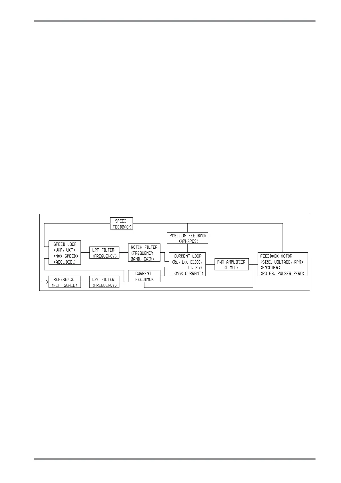
The Control Circuit consist of several functional blocks:
• Motor Feedback (size, voltage, rpm)
• Speed Feedback
• Speed loop (VKP, VKI)
• LPF Filter (frequency)
• Notch Filter ( frequency, band, gain)
• Current Feedback
• Current Loop (Rw, Lw, E1000, ID, SG)
• PWM Amplifier (limit)
• Position Feedback (APHAPOS)
Fig. 5.3 – Servosystem block diagram
5.4.1.1 HIGH POWER OUTPUT SECTION
The drive checks the current angular position in order to always keep a 90° angle
between the magnetic field generated by currents and the one generated by magnets on
the motor rotor.
The motor position is given by the feedback signals coming from the encoder or from the
resolver through an appropriate processing.
According to the information existing in the setting loop, the drive processes the
information concerning current width, frequency and angular position, and properly
commands the IGBT to supply the currents.
The current feedback is obtained by means of Hall sensors placed on U and V motor
phases.
The position feedback can be both the resolver and the encoder; inside the drive the two
signals are managed by two separate circuits in order to obtain the same final information
for the speed loop.