EasyManua.ls Logo

Moog DS2000 User Manual

Moog DS2000
142 pages
To Next Page IconTo Next Page
To Previous Page IconTo Previous Page
Page #8 background image
INDEX
DS2000 USER’S MANUAL (rev.C)
I.6
I.3 ACCIDENT PROTECTION
The safety instructions provided in this Manual are included to prevent injury
to personnel (WARNINGS) or damage to equipment (CAUTIONS).
WARNING: High Voltage. BUS BAR's can have voltage 810V
dc
even after switching off
(capacitive voltage). Discharge Time approx. 6 Minutes.
WARNING: High Voltage. The recovery resistor is connected to the BUS BAR’s and can
have voltage 810V
dc
.
WARNING: do not touch recovery resistor during operation to avoid scalds.
CAUTION: it is recommended to disconnect the drive and the EMC filters to carry out the AC
Voltage Tests of EN 60204-1 (1997), par.19.4, in order to not damage the Y-type capacitors
between phases and ground. Moreover the DC voltage dielectric test required by EN 50178
(1997), product family standard, has been carried out in factory as a routine test. The DC
Insulation Resistance Tests of EN 60204-1 (1997), par.19.3, may be carried out without
disconnecting the drive and the EMC filters.
CAUTION: when required for an emergency stop, opening U2-V2-W2 pins and closing motor
phases to resistors, must be preceded by disabling the axis. The delay time must be at least
30 ms.
CAUTION: in case of repetitive switching on and off, waits 1 minute between off and on.
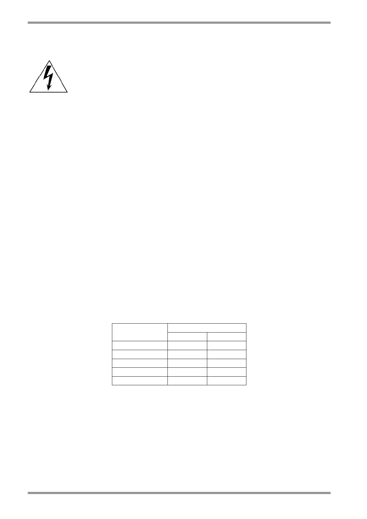
CAUTION: do not exceed the tightening torque of the table (but see proper data sheets for
the tightening torque of input capacitors and power modules and see section 2 of this manual
for the tightening torque of terminal blocks).
Tightening torque
Screw thread
[Nm] [lb in]
M3 1.00 8.85
M4 3.00 26.55
M5 6.00 53.10
M6 8.00 70.80
M8 20.00 177.00

Other manuals for Moog DS2000

Question and Answer IconNeed help?

Do you have a question about the Moog DS2000 and is the answer not in the manual?

Moog DS2000 Specifications

General IconGeneral
Input Voltage460 VAC ±10%, 3-Phase, 50/60 Hz
Output Current2000A
Control MethodDigital Control
Cooling MethodForced Air
Communication InterfaceEthernet
Protection FeaturesOvercurrent, Overvoltage, Undervoltage, Overtemperature
Regulation±0.1% of setpoint

Summary

Section 1 Description

1.1 INTRODUCTION

Introduces the DS2000 drive series and its coding system.

1.2 PRODUCT RANGE

Details the available DS2000 drive models and their specifications.

1.3 GENERAL FEATURES

Outlines the digital and flexible features of the DS2000 drives.

1.4 TECHNICAL DATA

Provides electrical and mechanical specifications for DS2000 drives.

Section 2 Wiring and Installation

2.1 INTRODUCTION

Introduces the section on installation, wiring, and cabling of DS2000 servo drives.

2.2 DIMENSIONS AND DRILLING JIG

Provides dimensions and drilling jig information for Size A DS2000 drives.

2.3 EXTERNAL FUSES

Recommends UL certified external fuses for short circuit protection.

2.9 CONNECTION CABLES

Specifies cable types and sizes for connecting DS2000 drives.

Section 3 Electromagnetic Compatibility (EMC)

3.1 INTRODUCTION

Describes recommended drive installation procedures following EMC standards.

3.2 EUROPEAN DIRECTIVE (89/336/EEC)

Explains compliance requirements with the European Directive 89/336/EEC.

3.3 FILTERS

Details the types of EMC filters recommended for DS2000 drives.

3.4 WIRING AND GROUNDING

Covers shielded cable requirements and grounding methods for EMC compliance.

Section 4 Starting

4.1 INTRODUCTION

Provides suggestions for the first start-up of a DS2000 drive.

4.2 DRIVE SETTING UP INFORMATION

Lists necessary information for drive setup, including motor and drive settings.

4.3 FIRST START-UP (ON TEST BENCH, FOR TESTING PURPOSES)

Guides on initial setup and testing of the DS2000 drive.

4.4 CONFIGURATION FOR INSTALLATION IN ELECTRICAL CABINET

Details settings for electrical cabinet installation and test bench configurations.

Section 5 Component Description

5.1 INTRODUCTION

Introduces the descriptions of the DS2000 Series Drives.

5.2 HIGH POWER INPUT SECTION

Describes the features and circuit of the high power supply section.

5.3 HIGH POWER OUTPUT SECTION

Details the three-phase output bridge and PWM technology used.

5.4 CONTROL SECTION

Explains the functional blocks of the control section, including loops.

Section 6 Commands

6.1 INTRODUCTION

Explains the function of the six keys on the drive front panel for menu navigation.

6.2 MOTOR PARAMETERS MENU

Details the menu for configuring motor parameters.

6.3 DRIVE PARAMETERS MENU

Describes the menu for configuring drive parameters.

6.4 CONTROL LOOPS PARAMETERS MENU

Outlines parameters for speed and current control loops.

Section 7 Troubleshooting

7.1 INTRODUCTION

Lists typical troubleshooting conditions and recommended actions.

7.2 FAULTS ON DRIVE POWER SUPPLY CIRCUIT

Addresses faults related to the drive's power supply circuit.

7.3 FAULTS ON DRIVE OUTPUT SECTION

Covers faults occurring in the drive's output section, like phase faults.

7.4 FAULTS ON FEEDBACK SECTION

Details faults related to encoder or resolver feedback detection errors.

Section 8 Restart Interlock Circuit (Optional)

8.1 INTENDED APPLICATION

Explains the intended application of the Restart Interlock Circuit (RIC).

8.2 RESTART INTERLOCK FUNCTION

Describes the restart interlock safety function and its compliance.

8.3 SAFETY REQUIREMENTS

Lists safety requirements for the restart interlock function.

8.5 RESTART INTERLOCK CONNECTIONS

Details the connections for the restart interlock circuit.

Appendix A: Motor Technical Data

APPENDIX A: Motor technical data

Provides guidance on obtaining motor technical data.

APPENDIX B: FC series technical data

Presents technical data for FC series low rpm special motors.

APPENDIX C: ACTIVE SOFTWARE RELEASE

Details active software releases and their added/removed functionalities.

APPENDIX D: OBSOLETE SOFTWARE RELEASE

Lists obsolete software releases and their replacements.

Related product manuals