SECTION TWO – WIRING AND INSTALLATION
DS2000 USER’S MANUAL (rev.C)
2.12
2.11 WIRING AND CONNECTORS
NOTE: Moog DS2000 drives are equipped with all the necessary connectors for a proper
operation. It is not necessary to indicate the connectors, or the recovery resistor in the
purchase order. All of them are included in the drive code.
All the drives (except D size and E size) are equipped with plug-in connectors to ensure a
quick connection of the drive to the switchboard and for Service activities (if applicable).
2.11.1 POWER CONNECTORS
Connectors differ according to the different drive sizes: please, refer to the following
descriptions and tables to detect the corresponding pin configuration; power connectors
bear a pinout label which makes pin detection easier.
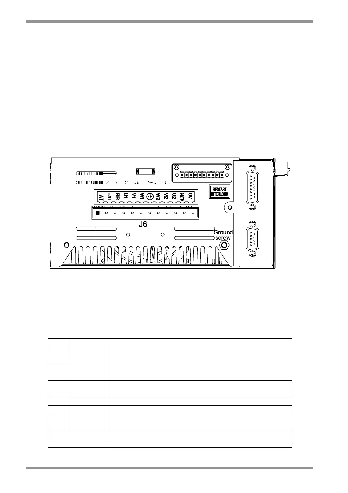
2.11.1.1 SIZE A and B POWER CONNECTOR
Note: Pin 1 is marked with the symbol “■”
Fig. 2.5 – Size A and B power connector
• J6 connector
- Mating connector: female. 12 pins, supplied with the drive, model Tyco 1-282960-2 or
1-796981-2 (Moog code AK4987).
Wire stripping: 7 mm. Tightening torque: 0.5Nm.
Pos. Name Function
1 ■ -AT - DC BUS AT
2 RR (+AT) External recovery resistor and +AT of DC BUS
3 RR External recovery resistor
4 U1 Phase "L1", three-phase voltage input 230/460V
ac
±10%
5 V1 Phase "L2", three-phase voltage input 230/460V
ac
±10%
6 W1 Phase "L3", three-phase voltage input 230/460V
ac
±10%
7 GND Motor ground (see also Ground screw)
8 W2 Phase "W2", motor three-phase output
9 V2 Phase "V2", motor three-phase output
10 U2 Phase "U2", motor three-phase output
11 +24V
12 0V (24)
Auxiliary voltage inputs 24 V
dc
±10%, 2A
(pin 12 is connected to drive logic 0)
Tab. 2.8 – J6 connector, size A and B