SECTION TWO – WIRING AND INSTALLATION
DS2000 USER’S MANUAL (rev.C)
2.28
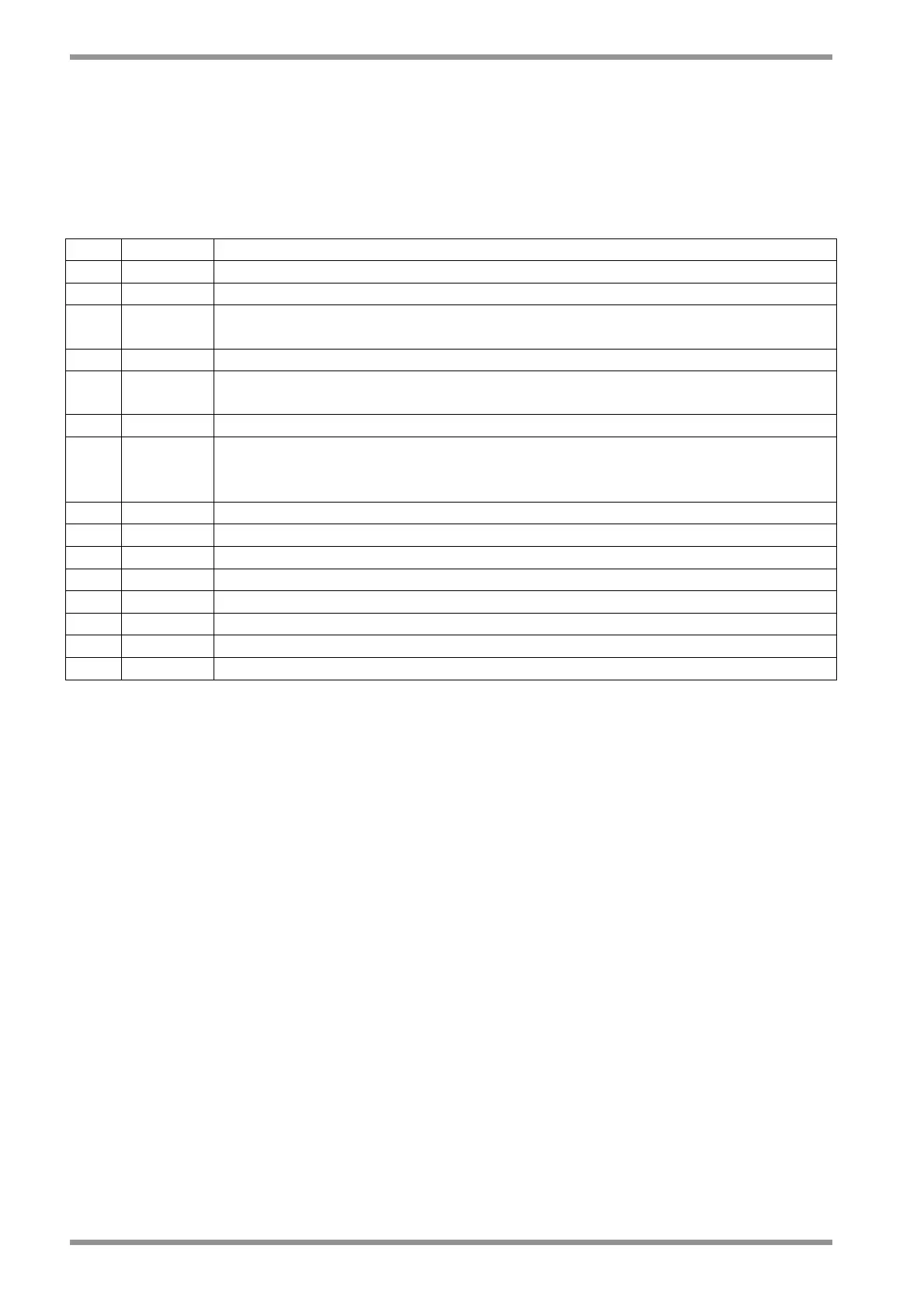
2.11.2.5.1 LIMIT SWITCHES CONNECTOR (J4)
When the special software 3.203 is used , the J4 connector becomes the Limit Switches
connector. An option card is needed together with this special software. The encoder cannot
be used as transducer and the ENC/OUT calibration of zero motor function is removed.
See Appendix C for other informations
Pos. Name Function
1 ■ N.C. Not Connected
2 N.C. Not Connected
3 CW LS
Input for CW Limit Switches. Normally connected to +24Vdc.
When the connection to +24Vdc is opened, the CW rotation is disabled.
4 N.C. Not Connected
5 CCW LS
Input for CCW Limit Switches. Normally connected to +24Vdc.
When the connection to +24Vdc is opened, the CCW rotation is disabled.
6 N.C. Not Connected
7 Tc/Vc
Input for torque/speed control.
When connected to +24Vdc the drive is in torque control.
When connected to 0L the drive is in speed control.
8 N.C. Not Connected
9 N.C. Not Connected
10 Common Common input for CW LS, CCW LS and Tc/Vc to be connected to 0L
11 N.C. Not Connected
12 N.C. Not Connected
13 N.C. Not Connected
14 N.C. Not Connected
15 N.C. Not Connected
Tab. 2.20A – J4 Limit Switches connector