SECTION FIVE – COMPONENT DESCRIPTION
DS2000 USER’S MANUAL (rev.C)
5.5
5.2.1.4.1 RECOVERY RESISTOR PROTECTION
In order to thermally protect the recovery resistor a set of parameters has been provided
in the menu. These parameters are:
• Resistor (RECOVERY RESIST. RESREC)
• Power (RECOVERY RESIST. POWER)
• And recovery coefficient (RECOVERY RESIST. COEFF)
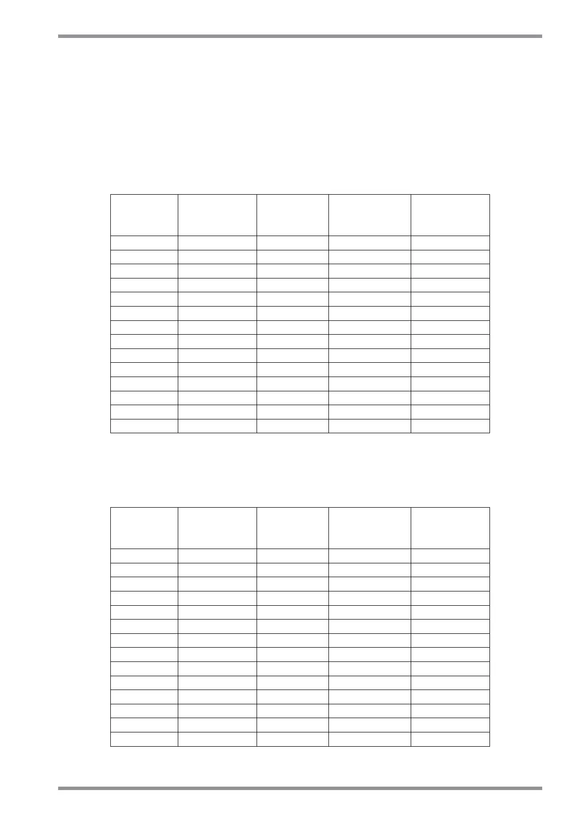
The parameters to be set with the standard recovery resistors are shown in tab 5.1.
Drive
Size
Max
peak
Current [A]
Resistor
Value [Ω]
Resistor
Power [W]
Coeff.
Value
3/9 10.0 75 (ext.) 100 71
4/12 10.0 75 (ext.) 100 71
6/15 14.7 51 (ext.) 200 53
8/22 14.7 51 (ext.) 200 53
14/42 22.7 33 (ext.) 250 43
20/45 62.5 12 (ext.) 370 74
25/70 62.5 12 (ext.) 370 74
30/90 62.5 12 (ext.) 370 74
50/140 75.0 10 (ext.) 750 21
60/180 75.0 10 (ext.) 750 21
100/300 192.3 3.9 (ext.) 1000 17
3/9 9.1 82 (int.) 150 84
4/12 9.1 82 (int.) 150 84
6/15 13.4 56 (int.) 150 78
Tab. 5.1 – Setting protection coefficient of recovery resistor
With 230 V
ac
mains power supply a more efficient series of recovery resistors can be used.
These optional resistors with the appropriate parameters are shown in tab 5.2.
Drive
Size
Max
peak
Current [A]
Resistor
Value [Ω]
Resistor
Power [W]
Coeff.
Value
3/9 10.0 47 (ext.) 100 69
4/12 10.0 47 (ext.) 100 69
6/15 14.7 33 (ext.) 250 45
8/22 14.7 33 (ext.) 250 45
14/42 22.7 22 (ext.) 240 69
20/45 62.5 6.8 (ext.) 370 63
25/70 62.5 6.8 (ext.) 370 63
30/90 62.5 6.8 (ext.) 370 63
50/140 75.0 5.6 (ext.) 750 19
60/180 75.0 5.6 (ext.) 750 19
100/300 192.3 2.2 (ext.) 1000 17
3/9 9.1 47 (int.) 150 87
4/12 9.1 47 (int.) 150 87
6/15 13.4 33 (int.) 150 80
Tab. 5.2 – Setting protection coefficient of recovery resistor