21
FILTERS (Continued)
CUTOFF
Matriarch’s CUTOFF knob specifies the Filter Cutoff frequency for both
VCF 1 and VCF 2 in a linked fashion. The SPACING knob is used to offset
the frequency of VCF 1, above or below the Cutoff Frequency of VCF 2.
FILTER MODE
This three-position switch defines how VCF 1 and VCF 2 are configured,
and how they will interact with each other.
HP / LP SERIES
In this mode, VCF 1 is configured as a High Pass filter and VCF 2 is
configured as Low Pass filter. Signal passes from the Mixer module into
VCF 1 (High Pass), and then is routed into VCF 2 (Low Pass). The mono
output signal from VCF 2 feeds both VCA 1 and VCA 2.
NOTE: This is the foundation for creating a Band Pass filter.
LP / LP STEREO
In this mode, VCF 1 and VCF 2 function independently as Low Pass filters.
Both receive the same signal from the Mixer module. VCF 1 is routed to
VCA 1, and VCF 2 is routed to VCA 2. This creates a true-stereo signal path
to the outputs.
HP / LP PARALLEL
In this mode, VCF 1 is configured as a High Pass filter and VCF 2 is
configured as a Low Pass filter. Both receive the same signal from the
Mixer module, and their outputs are combined into a monaural signal
that feeds both VCA 1 and VCA 2.
NOTE: This is the foundation for creating a Notch filter.
REFERENCE: To see Filter Mode Signal Flow diagrams see Page 72-73.
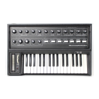
SPACING
Both VCF 1 and VCF 2 share the same Cutoff frequency value as
determined by the CUTOFF knob. This SPACING knob specifies an offset
in the value of the Cutoff frequency of VCF 1 in relation to the Cutoff
frequency of VCF 2. This knob is bipolar; so turning this knob clockwise
from center (+) increases the Cutoff frequency of VCF 1 to a value above
that of VCF 2. Turning this knob counterclockwise (-) decreases the Cutoff
frequency of VCF 1 to a value below that of VCF 2. In the center position,
the Cutoff frequency of VCF 1 is equal to the Cutoff frequency of VCF 2.
NOTE: The SPACING knob only aects the Cuto Frequency of VCF 1.
20Hz 20kHz
200Hz 2kHz