56
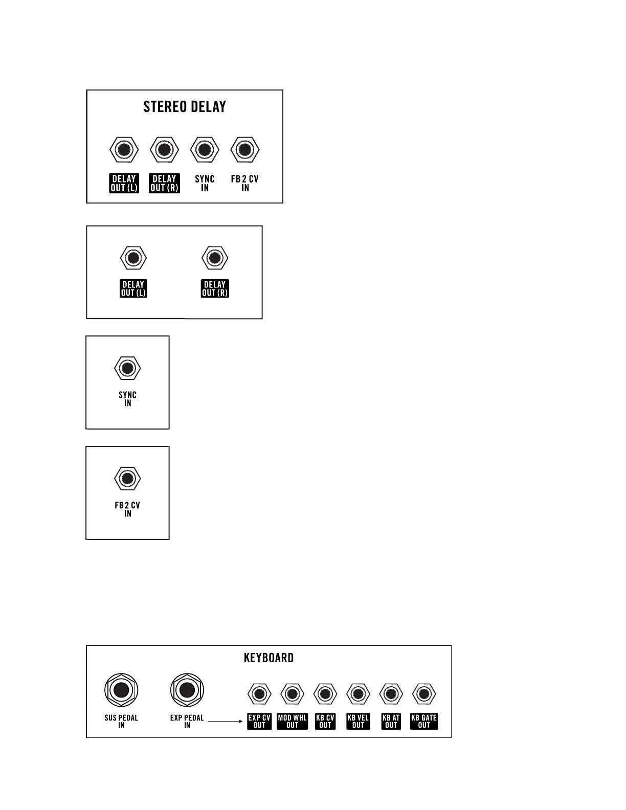
STEREO DELAY JACKS
The STEREO DELAY section of the rear panel relates
to the operation and control of the Stereo Delay.
Other jacks and controls for the Stereo Delay are
found on the front panel.
DELAY OUTS
The audio signals available at these outputs is the 100%
wet output of the individual Delay modules – Delay 1 and
Delay 2. By default, the output of Delay 1 is available at the
DELAY OUT (L) jack; the output of Delay 2 is available at
the DELAY OUT (R) jack.
AUDIO OUTPUTS: 10V peak-to-peak
SYNC IN
With the yellow SYNC button On (lit), the Stereo Delay Time will sync to the
rising edges of a clock or control signal received here. In this case, the Stereo
Delay TIME knob on the front panel will select divisions or multiples of the
sync’d clock rate.
CV INPUT: A rising signal > 3.6 Volts will create a Sync pulse.
DELAY FB 2 CV IN
The value of the CV signal received via this jack is summed with the current
value of the FEEDBACK knob in the Stereo Delay module on the front panel,
and is then used to modulate the Feedback amount for Delay 2 only.
CV INPUT: 0V to +8V
NOTE: The FB CV IN jack on the front panel will normally modulate the Feedback amount
of Delay 1 and Delay 2 by the same amount. By connecting a control signal to the FB 2 CV IN
jack, the Feedback modulation of Delay 1 and Delay 2 can be controlled individually.
The FB CV IN jack on the front panel will aect the Feedback amount of Delay 1, and
the FB 2 CV IN jack on the rear panel will aect the Feedback amount of Delay 2.
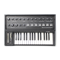
KEYBOARD JACKS
REAR PANEL (Continued)