38
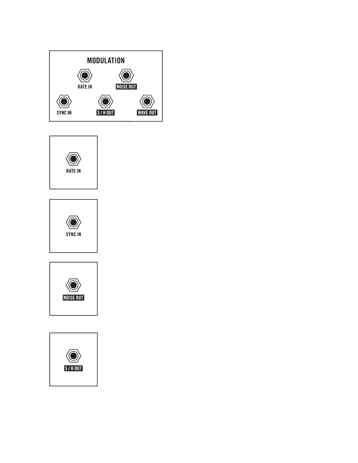
MODULATION PATCH POINTS
Control signals connected to the RATE IN and SYNC IN
patch point jacks can set the rate and reset the starting
point of the Modulation oscillator. In addition, three
patch point output jacks deliver Noise, S/H (Sample and
Hold), and the selected Wave as control sources that
can be used to modulate any controllable parameter.
RATE IN
A control signal connected to the RATE IN jack will determine the frequency
of the Modulation oscillator.
CV INPUT: -5V to +5V (1V/Oct)
TIP: Patch from the KB OUT jack on the rear panel to the RATE IN jack and adjust the
RATE knob accordingly to allow the Modulation oscillator to be “played” like an oscillator.
SYNC IN
A gate or trigger signal received at the SYNC IN jack will reset the Modulation
oscillator wave to its starting point, which allows for more predictable,
syncopated or creative use of the Modulation oscillator.
CV INPUT: Rising signal > 2.5 Volts will create a reset trigger. (0V to +10V)
NOISE OUT
The output of the internal White Noise generator is available at the
NOISE OUT jack, both as a modulation source, and as an audio signal.
CV/AUDIO OUTPUT: -8V to +8V
NOTE: A High Pass Filter (HPF) can be applied to the white noise signal using the
Global Settings, allowing the low frequency harmonic content of the noise signal to
be adjusted.
S/H OUT
Sample and Hold (S/H) is a stepped modulation effect, often used to “pulse”
the Cutoff frequency of a Low Pass filter with random values. At the beginning
of every modulation wave cycle, the Noise generator is sampled to acquire a
random value that can be used to modulate another parameter. That stream
of Sample and Hold values is available via this output.
CV OUTPUT: -8V to +8V
MODULATION (Continued)