30
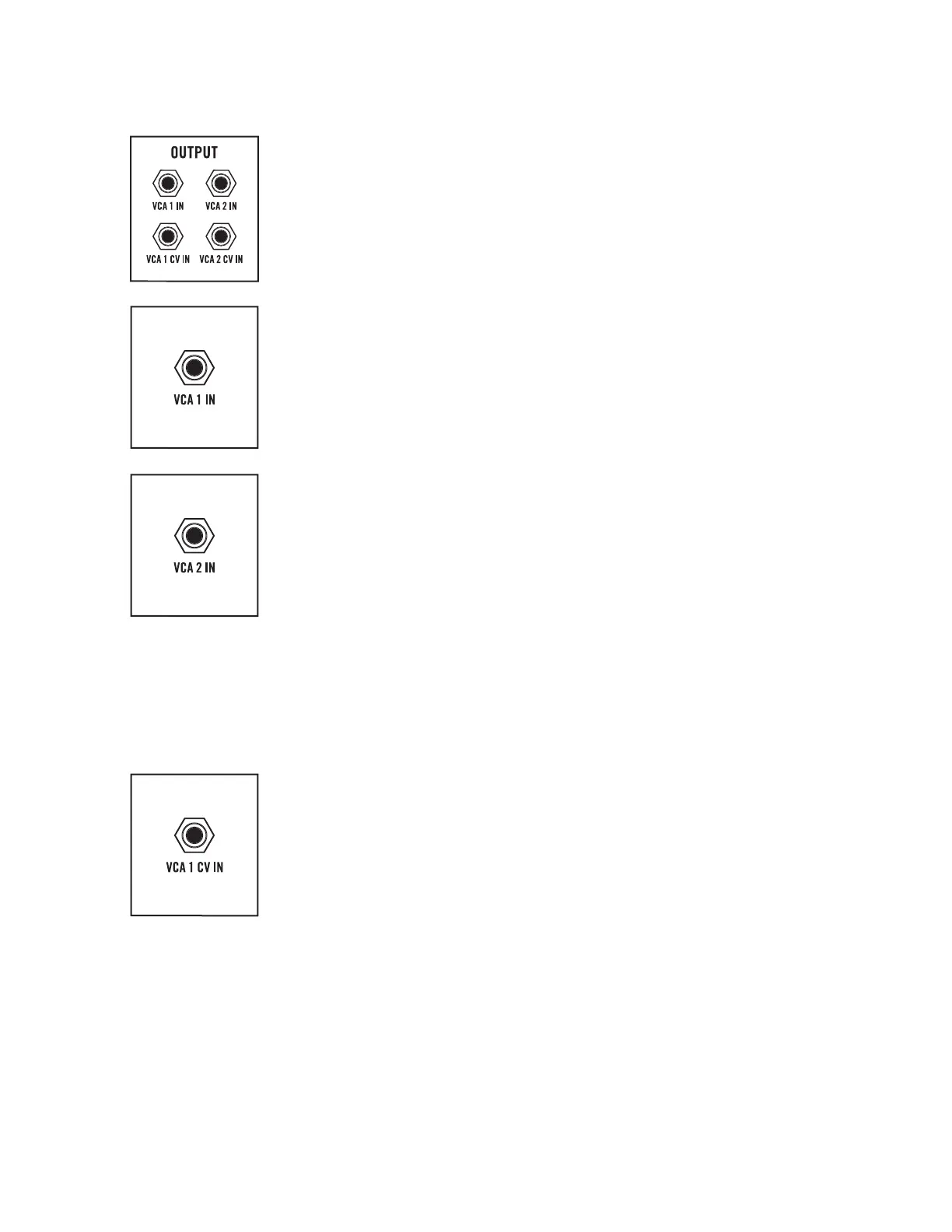
VCA PATCH POINTS
All of the VCA patch points are inputs. The upper row (VCA 1 IN and VCA 2 IN)
are audio inputs, while the second row (VCA 1 CV IN and VCA 2 CV IN) are
control signal inputs. Audio and control signals connected here will override,
or replace, any normalled connections.
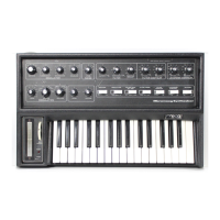
VCA 1 IN
The audio signal normally connected to the input of VCA 1 comes from
the Filter module. The exact nature of the audio source is determined by the
FILTER MODE switch located in the Filter module. Patching an audio signal
to this input overrides the Filter signal, allowing any audio source to be
processed by VCA 1 using the current settings.
AUDIO INPUT: -5V to +5V
VCA 2 IN
The audio signal normally connected to the input of VCA 2 comes from
the Filter module. The exact nature of the audio source is determined by the
FILTER MODE switch located in the Filter module. Patching an audio signal
to this input overrides the Filter signal, allowing any audio source to be
processed by VCA 2 using the current settings.
AUDIO INPUT: -5V to +5V
NOTE: The normal input source of VCA 1 and VCA 2 is determined by the FILTER MODE
switch. With this switch in the HP / LP SERIES position, the output of VCF 1 feeds into
VCF 2, and the composite output of VCF 2 is sent to the input of both VCA 1 and VCA 2.
In the LP /LP STEREO position, the output of VCF 1 is sent to the input of VCA 1, and
the output of VCF 2 is sent to the input of VCA 2. In the HP / LP PARALLEL position,
the summed output of VCF 1 and VCF 2 is sent to the input of both VCA 1 and VCA 2.
VCA 1 CV IN
A control signal connected here will determine the output level of VCA 1.
Normally, this control signal comes from one of the Envelope Generators,
as determined by the setting of the VCA MODE switch.
With the VCA MODE switch set to ENV or SPLIT, this jack can accept an -8V to
+8V signal that will control the level of sound prior to its arrival at VCA 1. In either
setting, applying an LFO to this input can be used to create a tremolo effect.
With the VCA MODE switch set to DRONE, a control signal (0V to +8V) applied
here will set the level of VCA 1 from minimum (0V) to maximum (+8V) level.
CV INPUT: -8V to +8V (VCA MODE switch set to ENV or SPLIT); 0V to +8V (VCA
MODE switch set to DRONE)
OUTPUT (Continued)