16
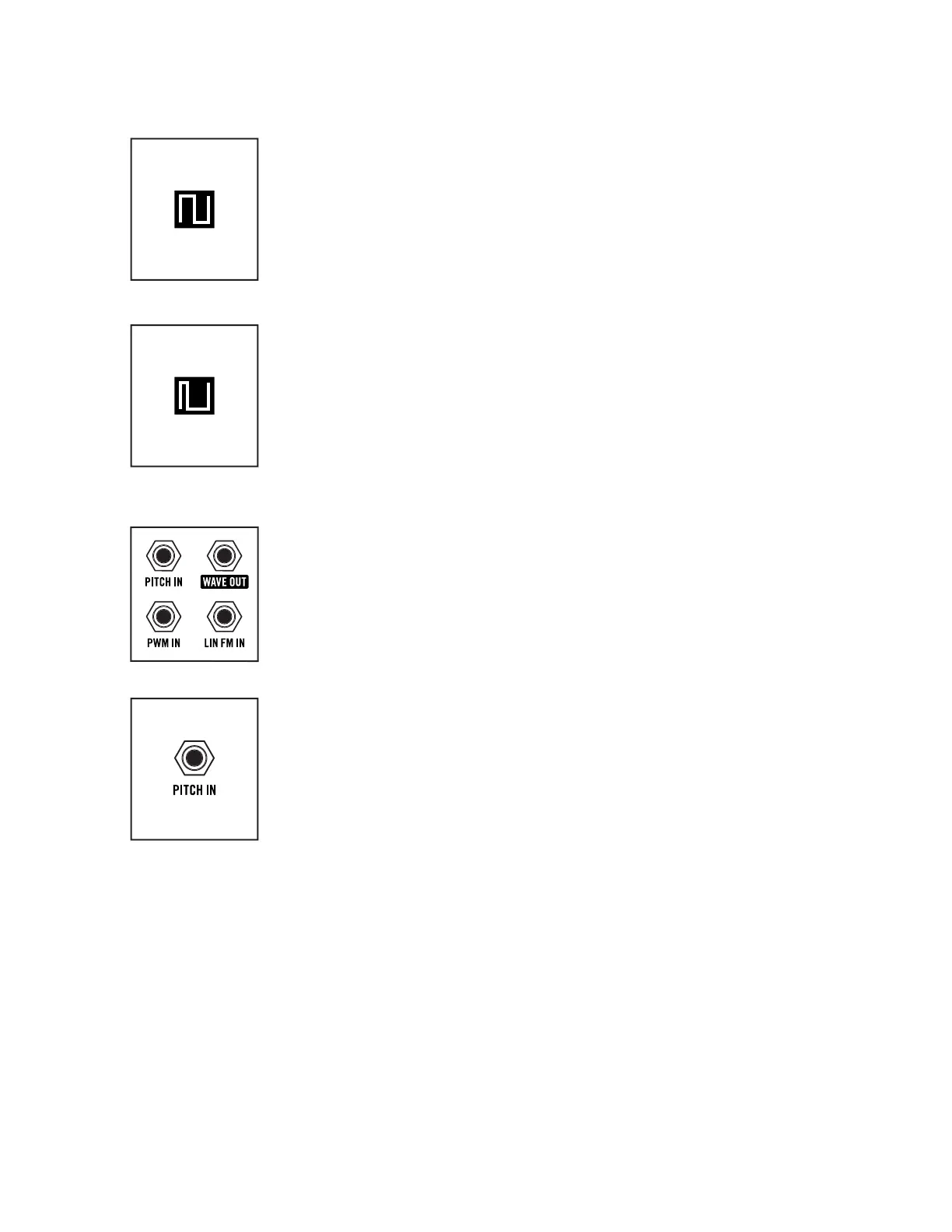
SQUARE
A Square wave is simply a Pulse wave with a 50% duty cycle, meaning that in
a single cycle, it is on half of the time and off half of the time. If the frequency
is 440 Hz, it turns on and off 440 times every second. Square waves have a
hollow sound and provide a rich starting point for clarinet and bass sounds.
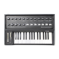
NARROW PULSE
As a Pulse wave continues to grow narrower, the resulting timbre takes
on a more reedy, or nasal tone and is used to make oboe and even classic
“clav” sounds.
TIP: Varying the duty cycle of the Pulse wave can result in a wide variety of lush
or chorus-like sounds. With at least one oscillator set to produce a Pulse wave, try
experimenting with the PULSE WIDTH AMT knob in the Modulation module and
listen to how modulating this waveform aects the sound.
OSCILLATOR PATCH POINTS
Each Matriarch oscillator is equipped with versatile patch points, allowing for a
variety of modulation possibilities, including Linear FM (Frequency Modulation)
and PWM (Pulse Width Modulation).
NOTE: The patch points for each oscillator are identical.
PITCH IN (Exponential Frequency Modulation)
A control signal connected to this input will modulate the Pitch (Frequency)
of a patched oscillator and all subsequent oscillators, unless a subsequent
oscillator is also receiving a modulation signal via its own PITCH IN jack. This
input voltage is added to the voltage from the note played on the keyboard.
NOTE: Connecting a modulation source to the PITCH input on Oscillator 1 will aect
the Pitch of Oscillators 1, 2, 3, and 4. Connecting an additional modulation source
to the PITCH input of Oscillator 2 will aect the Pitch of Oscillators 2, 3 and 4, and
will prevent the modulation signal arriving at the Oscillator 1 PITCH input jack from
modulating these oscillators.
TIP: By connecting a modulation source to the Oscillator 1 PITCH IN jack, and a “dead
patch” to the Oscillator 2 PITCH IN jack, only Oscillator 1 will receive the modulation
signal. A dead patch is a cable connected to a patch point with no connection on the
opposite end, used to interrupt normalized signal paths.
CV INPUT: -5V to +5V Control Voltage (1V/Oct)
OSCILLATORS (Continued)