34
STEREO DELAY (Continued)
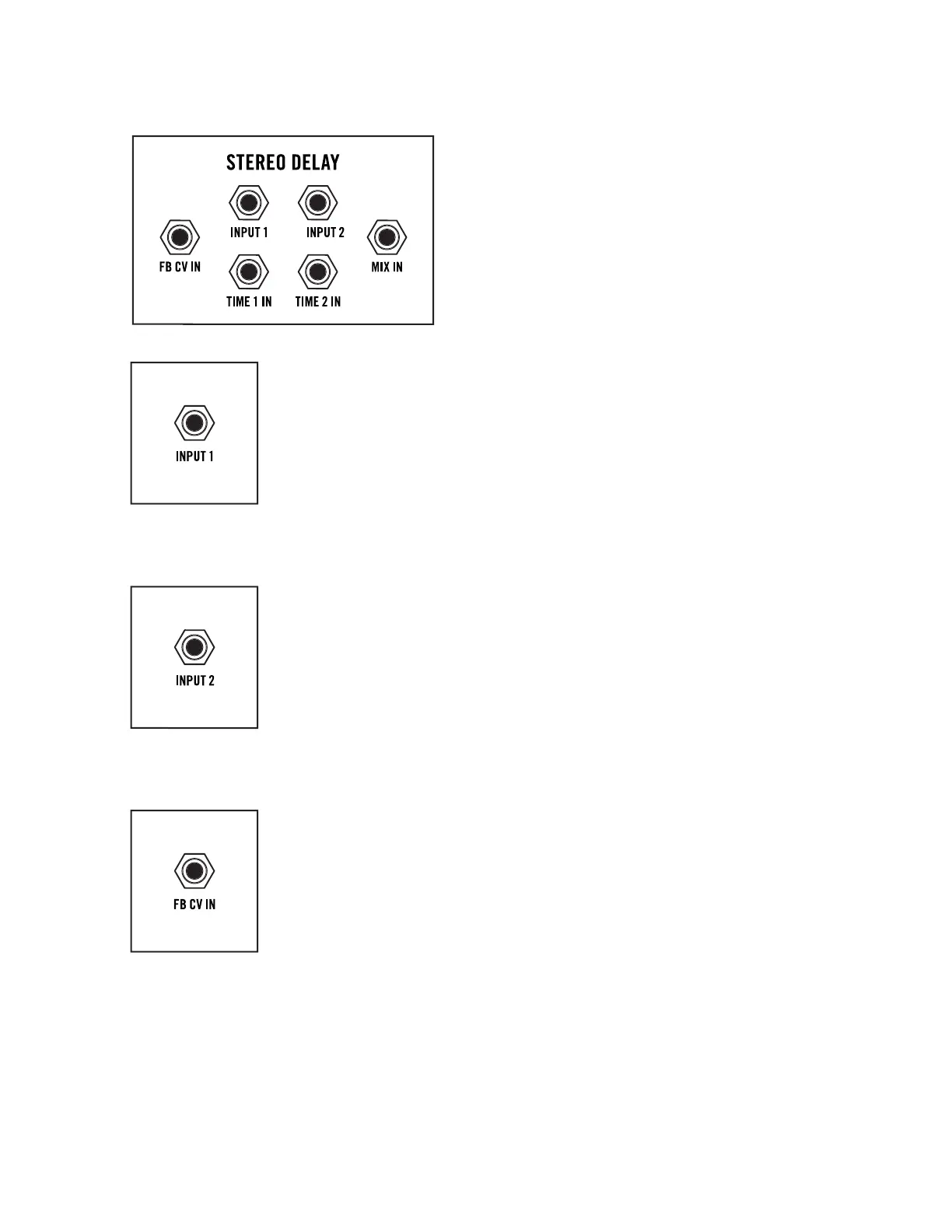
STEREO DELAY PATCH POINTS
The Stereo Delay module features both Audio and
Control signal inputs. The Audio inputs override
and replace the normal hardwired audio connections.
The Control inputs are summed with the current
value of their corresponding panel knobs.
NOTE: Additional Stereo Delay patch points are located
on the rear panel.
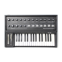
INPUT 1
Normally, the input to Delay 1 comes from VCA 1. An audio signal connected
the INPUT 1 jack replaces the VCA 1 signal, and will be processed by the first
delay module (Delay 1). The output of Delay 1 will appear at the left channel
of all associated outputs.
AUDIO INPUT: 10V peak-to-peak (-5V to +5V)
NOTE: The MIX knob controls the balance between the output of the VCAs and the
output of the Stereo Delay module.
INPUT 2
Normally, the input to Delay 2 comes from VCA 2. An audio signal connected
the INPUT 2 jack replaces the VCA 2 signal, and will be processed by the
second delay module (Delay 2). The output of Delay 2 will appear at the right
channel of all associated outputs.
AUDIO INPUT: 10V peak-to-peak (-5V to +5V)
NOTE: The MIX knob controls the balance between the output of the VCAs and the
output of the Stereo Delay module.
FB CV IN (Feedback Control Voltage Input)
The value of a Control signal connected to this input will be summed with the
current position of the FEEDBACK knob to determine the amount of Feedback
for Delay 1 and Delay 2.
CV INPUT: -5V to +5V
NOTE: A control signal connected to the FB 2 CV IN jack on the rear panel will control
the Feedback amount of Delay 2 independently from Delay 1. In this case, a control
signal connected to the FB CV IN jack on the front panel will only aect the Feedback
amount of Delay 1.
TIP: Connecting a modulation source to the FB CV IN jack, and a “dead patch” to the
FB CV 2 IN jack on the rear panel will prevent the modulation signal from reaching
Delay 2. A dead patch is a cable connected to a patch point with no connection on
the opposite end, used to interrupt normalized signal paths.